12
IOM (Safety) - Installation, Operation and Maintenance
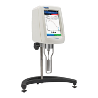
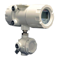
Optical Oxygen Analyzer
The OXYvisor Optical Oxygen Analyzer includes a 316 SS pipe-mount bracket for eld mounting. Additional components needed to produce a
functional oxygen measurement include a Barben Oxygen Sensor (BOS) and Pt1000 RTD (Resistance Temperature Sensor).
It is important that the product Name Plate (Figure 3) is reviewed to properly identify the product, it’s power input, and the specic hazardous area
markings for the actual unit. It is equally important that the installation control drawing referenced in Table 4, is fully understood and followed along with
the inclusion of any applicable federal, state and local codes.
Section 3 - Installation
3.1 Installaon Overview
3.2 Inspecon of the Analyzer Shipment (consignment)
Check the packaging and the device for visible damage caused by inappropriate handling, during shipping. Close attention should be paid to the
analyzer enclosure for signs of impact during shipping. All threads should be inspected for burrs and any residual packing material should be removed.
Report any claims for damages immediately to the shipping company.
T
ake pictures and retain damaged parts for clarication. Check the scope of
delivery by comparing the shipping documents with your order for correctness and completeness.
The OXYvisor is used to quantitatively measure the amount of oxygen in a gaseous or liquid sample. The analyzer may only be installed as
specied in these instructions per its intended use. Modications to the analyzer which are not expressly referred to within these instructions will result in
an application which is not in accordance with the intended use. Such modications are then the exclusive responsibility of the user.
Do not use any damaged or incomplete devices. Danger of explosion in hazardous areas.
OXYvisor Model Number Type of Protection Installation - Control DWG
BOA-DC-1-SFP-B-SI/AM
Zone 1 IIC 2P0345 (Zone 1)
BOA-AC-1-SFP-B-SI/AM
BOA-DC-2-SFP-B-SI/AM
Class I, Division 2
Groups A,B,C,D
2P0335 (Class I, Div. 2)
BOA-AC-2-SFP-B-SI/AM
BOA-DC-3-SFP-B-SI/AM
Zone 2 IIC 2P0346 (Zone 2)
BOA-AC-3-SFP-B-SI/AM
Table 4 - OXYvisor
3.3 Weight
3.4 Tools
The approximate weight of the analyzer is 13.7 lb (6.2 kg).
Suggested tools to complete the installation are listed below:
• M8 or Small crescent Wrench (Used for 2” pipe mount bracket installation)
• Large athead Screwdriver (Used to mount analyzer to mounting bracket)
• Small athead Screwdriver (used for wiring)
• 36mm Open End or large adjustable wrench (Used to adjust jam nut between analyzer and junction box)
• 2 mm Hex Key or driver to lock the rear compartment
• Loctite 577, P/N: B8008-1014 (Only if J-Box needs re-orientation, see Section 5.4.2
3.5 Mounng the Analyzer
Factors to consider when mounting the analyzer:
• Analyzer/Pipe Mount Orientation: The analyzer and pipe mount kit can be mated/arranged to mount to either a vertical (Fig. 6) or horizontal pipe
(Fig 7). See Fig. 5 and 6.
The front compartment contains the display and electronics boards. It is secured via the 2 mm Hex Lock and is not meant to be opened
in the eld at any time. If it is opened, follow the instruction to tighten and secure the Rear (Wiring) Compartment lid. Section 5.4.1.
Section 3
Installation
OPTICAL BUSHING / MAIN ENCLOSURE - The optical bushing going into the upper main enclosure must not be removed nor turned.
There is a locking screw (4 mm Hex) to prevent this.
OPTICAL BUSHING / JUNCTION BOX - To maintain the safety aorded by this analyzer do not change the orientation, remove or re-
install the Junction Box in the eld.
UNUSED ENTRIES - Unused entries shall be closed with suitable certied Ex db blanking elements with a minimum IP66 rating.
3.5.1 Orientaon of the Juncon Box
The Junction Box is not to be adjusted, removed or re-installed in the eld for Zone 2 applications. Doing so will aect the safety
evaluation and certicates of the device.
The Junction Box is tted and located at the bottom of the analyzer with a front-forward orientation as standard and as shown in Figure 5 & 6. The
orientation is locked into position via a Jam Nut and the 3/4” NPT threads (mating to Fiber Optic Bushing) are sealed with a thread-sealant. The
orientation can be specically selected in the ordering process or sent back to the factory for adjustment.
1. Locate the proper height for the HMI and display so that it is easily accessible for user
2. Install the L-bracket to the analyzer by tightening down the (4) M6 slotted screws.
3. Install the U-bolt around the pipe at the proper height into the L-bracket and tighten the M8 nuts
4. Double check tightness of the screws and bolts
3�5�2 OXYvisor - Pipe-Mount to Vercal Pipe
 Loading...