14
IOM (Safety) - Installation, Operation and Maintenance
Optical Oxygen Analyzer
Input /Output wiring requirements:
• 26 to 16 gauge (IEC .400 to 1.25)
• Copper, stranded wire
• Minimum 300V Insulation
• Tightened (torque) to .22 to .25 Nm
Input / Output Wiring
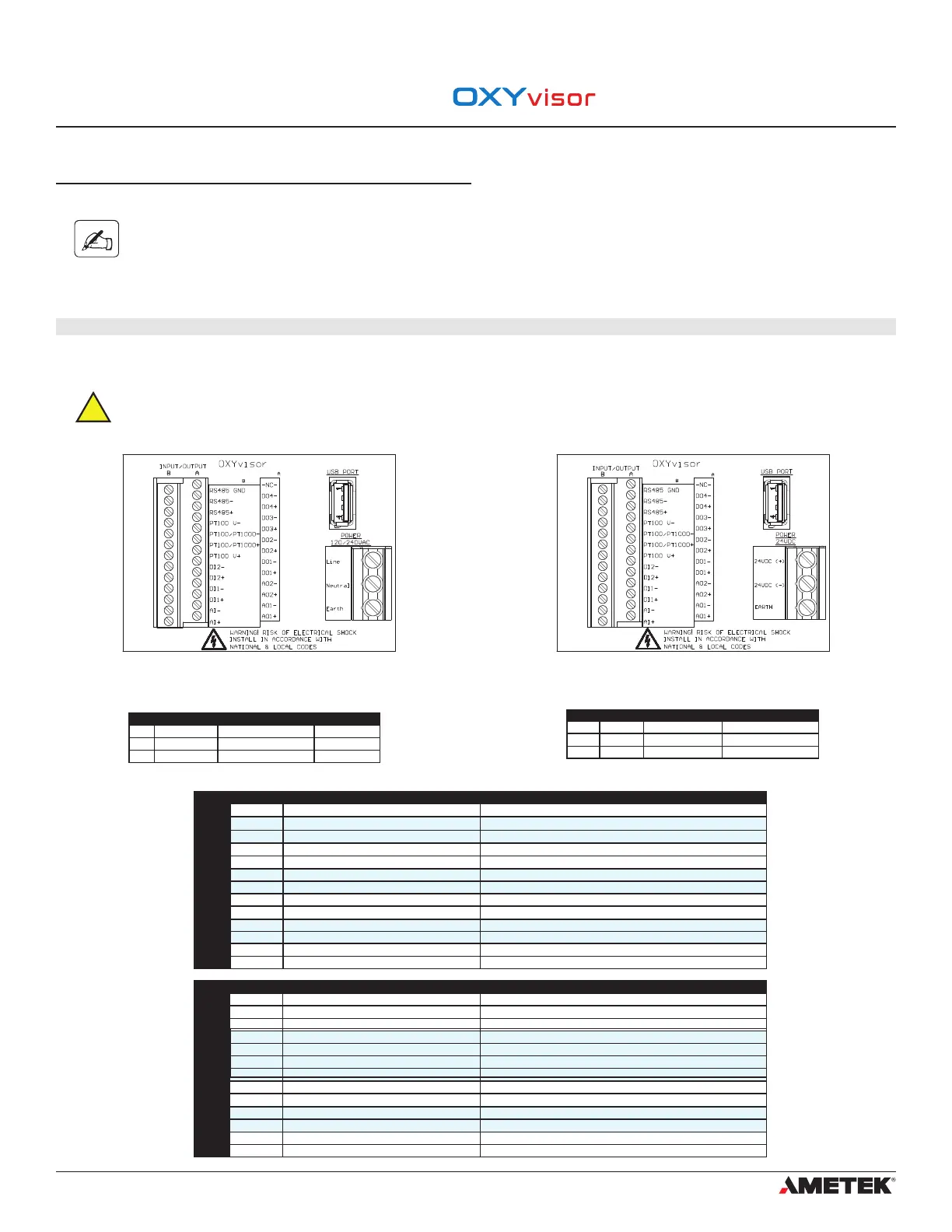
Input/Output wiring for the OXYvisor is located on the left side of the board as shown in Figure (8) & (9). For wiring assignments see Table (7).
Please note that the 24VDC version of the analyzer is a 4-wire device. It has separate wiring for power and
signal (not a loop powered device).
3.6.3 DC Powered Analyzer
DC Power
OXYvisor analyzers ordered with DC power input will have a termination board labeled with “24VDC (+)”, “24VDC (-)”, and “Earth” (Ground) as
shown in Figure (9).
Analyzer - Power Supply Connections (DC Version)
The OXYvisor control unit can operate using 24 VDC +/-10%. When energized by mains the 24 V DC supply must be from a Class2 or LPS source,
OR that a fuse (1 A) will be required in the installation.
3.7 Wiring - Input/Outputs
Terminal
Terminal
Terminal
Terminal
Figure 8 - AC Terminal Board - Located in Rear (Wiring) Compartment Figure 9- DC Terminal Board - Located in Rear (Wiring) Compartment
Section 3
Installation
Label Terminal Description Function
Line Power 120/240VAC 85-240 VAC 47/63Hz Input Power Line Power Wiring
Neutral Power 120/240VAC 85-240 VAC 47/63Hz Input Power Neutral Power Wiring
Earth Power 120/240VAC Earth Terminal Earth Terminal
Label Terminal Description Function
24VDC (+) Power 24VDC 21.6 - 26.4 VDC Positive DC Power Wiring
24VDC (-) Power 24VDC 21.6 - 26.4 VDC Negative DC Power Wiring
Earth Power 24VDC Earth Terminal Earth Terminal
AC TERMINAL BOARD POWER WIRING
DC TERMINAL BOARD POWER WIRING
Input / Output
TERMINAL -
B
Label Description Function
RS485 GND Serial Communication Modbus RS485 RTU Common Wire
RS485 - Serial Communication Modbus RS485 RTU Data Negative Wire
RS485 + Serial Communication Modbus RS485 RTU Data Positive Wire
PT100 V - PT1000 4-wire or jumper to next terminal PT100 4 wire RTD input, Drive Voltage negative wire (black)
PT100/PT1000 - PT1000 Temperature Sensor PT1000 negative wire then jumper to PT100 - terminal above
PT100/PT1000 + PT1000 Temperature Sensor PT1000 positive wire then jumper to PT100 + terminal below
PT100 V+ PT1000 4-wire, 3’rd wire or jumper to above terminal PT100 4 wire RTD input, Drive Voltage positive wire (red)
DI2 - Digital Input 2 (0 VDC) Powered Digital input, Negative Wire, Connect to external switch for remote Test Gas Insert
DI2 + Digital Input 2 (5 VDC) Powered Digital input, Positive Wire, Connect to external switch for remote Test Gas Insert
DI1 - Digital Input 1 (0 VDC) Powered Digital input, Negative Wire, Connect to external switch for remote AutoCal Initiation
DI1 + Digital Input 1 (5 VDC) Powered Digital input, Positive Wire, Connect to external switch for remote AutoCal Initiation
AI1 - Analog Input (0 VDC, 4-20mA) Analog Input, Negative Wire, 24VDC Powered,. Programmable for Temperature or Pressure
AI1 + Analog Input (24 VDC, 4-20mA) Analog Input, Positive Wire, 24VDC Powered,. Programmable for Temperature or Pressure
Input / Output
TERMINAL
- A
Label Description Function
-NC- Not used Not used
DO4 - Relay Output 4 (24VDC, 0.05A pilot duty, 0.4A resistive load) Programmable, Isolated Relay Negative wire
DO4 + Relay Output 4 (24VDC, 0.05A pilot duty, 0.4A resistive load) Programmable, Isolated Relay Positive wire
DO3 - Relay Output 3 (24VDC, 0.05A pilot duty, 0.4A resistive load) Programmable, Isolated Relay Negative wire, (Process Gas Relay if AutoCal is used)
DO3 + Relay Output 3 (24VDC, 0.05A pilot duty, 0.4A resistive load) Programmable, Isolated Relay Positive wire, (Process Gas Relay if AutoCal is used)
DO2 - Relay Output 2 (24VDC, 0.05A pilot duty, 0.4A resistive load) Programmable, Isolated Relay Negative wire, (Span Cal Relay if AutoCal is used)
DO2 + Relay Output 2 (24VDC, 0.05A pilot duty, 0.4A resistive load) Programmable, Isolated Relay Positive wire, (Span Cal Relay if AutoCal is used)
DO1 - Relay Output 1 (24VDC, 0.05A pilot duty, 0.4A resistive load) Programmable, Isolated Relay Negative wire, (Zero Cal Relay if AutoCal is used)
DO1 + Relay Output 1 (24VDC, 0.05A pilot duty, 0.4A resistive load) Programmable, Isolated Relay Positive wire, (Zero Cal Relay if AutoCal is used)
AO2 - Analog Output 2 (4-20mA) Active Analog Output (Negative wire, Active 24 VDC)
AO2 + Analog Output 2 (4-20mA) Active Analog Output (Positive wire, Active 24 VDC)
AO1 - Analog Output 1 (4-20mA) Active Analog Output (Negative wire, Active 24 VDC)
AO1 + Analog Output 1 (4-20mA) Active Analog Output (Positive wire, Active 24 VDC)
INPUT / OUTPUT WIRING
 Loading...