7
IOM (Safety) - Installation, Operation and Maintenance
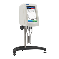
Optical Oxygen Analyzer
2�1 OXYvisor - BOA Oxygen Analyzer Specicaons
Section 2 - Technical Product Specifications - RATINGS
OXYvisor Oxygen Analyzer Specications
Power Supply - Selectable as AC or DC via Product Selection Nomenclature
AC Power 85-240* VAC, 47-63 Hz, 6W
(AC, “4-wire,” line powered analyzer), (*Zone 1 and CID2 can be up to 264 V)
DC Power 24 V DC +/-10% 5W (Class 2 / LPS source) (DC, “4-wire,” line powered analyzer. Not a 2-wire loop powered transmitter)
Environmental (Allowable Ambient Conditions)
Operating Temperature -20 to +55ºC (-4 to 131ºF)
Storage Temperature -20 to +65ºC (-4 to 149ºF)
Max. Operating Relative Humidity 95%, non-condensing
Max Altitude Maximum altitude up to 2,000 meters (6,561 ft)
IEC IEC Installation Category II and Pollution Degree 2
Physical
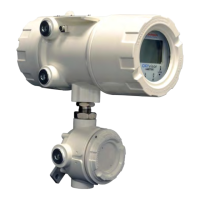
Main
Enclosure and
Junction Box
Ratings IP66 and NEMA 4x, protected against dust and high pressure water ingress. Corrosion resistant.
Material Type Aluminum pressure die-casting with yellow chromating and chemically resistant paint
Conduit Entries Main enclosure = QTY 4, junction box = QTY 2, 3/4” FNPT or M25 x 1.5 6H conduit entries
O-Ring Seals Silicone VMQ rubber
Dimensions H x W x D
(combined) 12.0 x 5.5 x 11.0 inches (30.5 x 14.0 x 28 cm)
Weight
(total/combined) 13.7 lb (6.2 kg)
Liquid Crystal Display Viewing = 79 (W) x 40 (H) mm, 240 x 128 dots, FSTN / Positive / Transective
HMI Touch-Keys
(through-the-glass) (4) proximity switches, infrared contacts for interactive user interface at HMI
Input Information
Sensor Inputs
Optical O
2
(1) O
2
optical input BOS1, BOS2 or BOS3 sensor (SMA connector)
RTD - Temp (1) Pt100 or Pt1000 4-wire RTD Inputs (isolated)
Analog Input
(1) 4-20 mA input (24 Vdc active from
OXYvisor) - User congurable for Temperature or Pressure
transmitter
Pressure Sensor (1) On-board integrated pressure sensor measures and compensates for ambient pressure conditions
Digital Inputs (2) optically isolated inputs, 5 Vdc powered, remote initiation of automatic calibration and live validation gas
Output Information
Analog Outputs (2) Programmable current outputs with galvanic isolation, 4 to 20 mA (Active), Linear or Bi-Linear, 24 Vdc
Digital Outputs (Alarm/Relays) (4) Programmable relays, optically isolated, passive, 24Vdc, 0.05A pilot duty, 0.45 A general use/ resistive load.
Digital Communication (1) Modbus RTU serial protocol RS485 - Two way Communication
Table 1 - OXYvisor
Barben Oxygen Sensors (BOS), are sold separately or as parts of an integrated (SCP) package with the OXYvisor. The sensors consist of a ber
optic cable with SMA termination at one end, for connection to the OXYvisor, and the other end, an oxygen sensing luminophore, to be placed into
the process or sample stream. For additional information on BOS sensors, please refer to the OXYvisor IOM, OXYvisor data sheet or BOSx Sensors
product data sheet. The BOSx oxygen sensors are shown on the installation control drawings.
2.2 BOS Sensor Overview (determines operang range for OXYvisor)
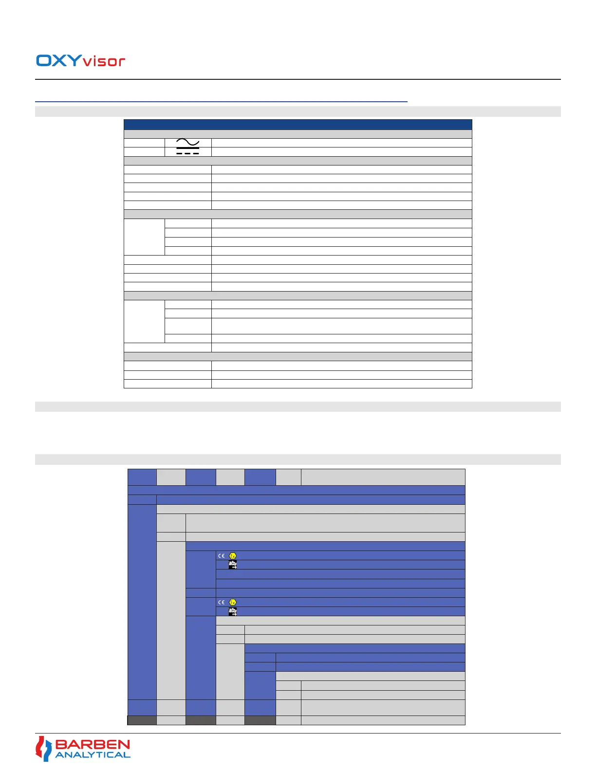
2�3 OXYvisor Conguraon - Product Model Selecon
Table 2 - OXYvisor
Analyzer Power
Agency
Approval
Sensor
Style
Mounting
Orientation
Conduit
Entries
OXYvisor Base Model Number
BOA
OXYvisor - Barben Oxygen Analyzer
Input Power
DC 21.6 to 26.4 VDC, 5W (4-wire, line powered analyzer, this is NOT a loop powered analyzer. Requires two
wires for DC power and two separate wires for 4-20 mA output)
AC 85 to 240* VAC, 47-63 Hz, 6 W
(4-wire, line powered analyzer), (*Zone 1 and CID2 can be up to 264 V)
Agency Approval
1
II 2 G Ex db op is IIC T4 Gb || ATEX
Ex db op is IIC T4 Gb
|| IEC / EU
Class I Zone 1 AEx db op is IIC T4 Gb || US (NEC 505)
Ex db op is IIC T4 Gb || CA (CEC Section 18)
2 Class I Division 2 Group A, B, C, D T4a || US (NEC 500) and CA (CEC Annex J18)
3
II 3 G Ex ec [ic] op is IIC T4 Gc || ATEX
Ex ec [ic] op is IIC T4 Gc || IEC / EU
Sensor Style
SFP Standard Fiber Patch
X* Saved for future use - Integral Wands with lengths (2.5, 5.0 and 10 M)
Mounting Orientation
B Junction Box placed below main enclosure, ber optic exits bottom
(as shown)
Y** Saved for future use - other orientations w/ display and JB
Conduit Entries
SI 25 mm Conduit Entries
AM 3/4” FNPT Conduit Entries
Analyzer Power
Agency
Approval
Sensor
Style
Mount
Orientation
Conduit
Entries
BOA DC 2 SFP B AM Typical Analyzer Model Number (Example)
Section 2
Technical Product Specication
 Loading...