21
IOM (Safety) - Installation, Operation and Maintenance
Optical Oxygen Analyzer
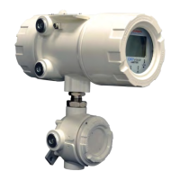
All programming of the OXYvisor analyzer can be accomplished either through the keypad or through the OXYvisor software provided with the
unit. Consult the OXYvisor IOM and/or the OXYvisor IM Software for detailed operation instructions. With regards to safety, the OXYvisor was tested to
the standards stated in Section 2.7, while congured and loaded to the worst case conditions.
Section 4 - Operations
4.1 Operaons Overview
Section 4
Operations
The analyzer will show any active error codes on the active display, along with recording the error into the log and throwing any associated alarm. The
error codes are broken into two main groups, “N” for non-critical alarms and “X” for critical. “N” Non-critical alarms, Table 8, indicate an issue that should
be immediately investigated and resolved, however it has been determined that the measurement is still likely good and it is unnecessary to fault the
output. A “X” critical fault, Table 9, identies something that likely renders the device immediately faulty and fails the 4-20 mA outputs.
4.2 Sub-Menu - Error Codes
Error
Code
N-type (non-critical) Error Description Trouble shooting and things to check
N12
Optical measurement error. Optical board is not able to perform the
calculation from the sensor input available.
Check O
2
sensor connections. Check sensor tip for damage. Place sensor into Zero gas and observe. Consult factory.
N13 Phase Angle “out of range”
This is a common error for BOS3 sensors while exposed to air. Place sensor in zero gas and observe. Check O
2
sensor connections.
Check sensor tip for damage. Consult factory.
N15 Data sent to the Optical Board is wrong or out of bounds. Consult factory.
N21 Data present in ash is in an unrecognized format.
Consult factory. Flash type error. User will be required to roll-back to previous rmware rev or will have to erase the log in order
to proceed.
N25 Ambient pressure reading is out of range (500 mBar to 11 mBar).
Check local ambient conditions. Congure for manual pressure input and give best estimate value for measurement and calibration
pressure(s).
N35
Modbus validation engine has agged an error and some unauthorized
operation was performed over Modbus.
Check the Modbus master device. If a Modbus to USB cable is being used, check cable requirements and replace.
N36
Unauthorized register was accessed via the Modbus. It can be agged
while writing or reading via Modbus.
Check your Modbus master device and any converters.
N41
Sensor temperature protection. The sensor operating temperature is
out of range.
Investigate the process temperature. Process temp must be greater than -10 °C and less than 90 °C. Reduce process or sample
temperature.
N42 Zero phase angle is out of the allowed limits (45° to 70°) Check calibration gas ow during calibration. Check for leaks. Check sensor connections. Error is cleared with a proper calibration.
N44 Auto calibration zero value has crossed the user dened tolerance limit.
Check calibration gas o
w during calibration. Check for leaks. Check sensor connections. Error is cleared with a proper calibration.
N45 Auto calibration span value has crossed the tolerance limit. Check calibration gas ow during calibration. Check for leaks. Check sensor connections. Error is cleared with a proper calibration.
N46 The O
2
reading exceeds the user dened 20mA value. Check the 20 mA point. Increase the 20 mA point or consider bi-linear 4-20 mA output to account for this high O
2
condition.
N47 The O
2
reading is lower than user dened 4mA value. Check the 4 mA point. If 4 mA point is set to zero, re-perform a zero calibration.
N51 RTD not detected in the system.
Check the wiring and any jumpers at the termination board. Remove the sensor and check for proper Pt1000 resistance with
Multimeter.
N52 Temperature reading is out of user dened 4-20 mA limits Check the 20 mA point. Increase the 20 mA point or consider bi-linear 4-20 mA output to account for this high O
2
condition.
N53 Analog output 1, AO1, is open circuit.
Check wiring to device. OXYvisor is (active, powered output) so make certain the receiving device is passive (non-
powered). If AO1 is not planned to be used, set to inactive
N54 Analog output 2, AO2, is open circuit.
Check wiring to device. OXYvisor is (active, powered output) so make certain the receiving device is passive (non-
powered). If AO2 is not planned to be used, set to inactive
N56
Analog input, AI, pressure value is outside of user dened 4-20 mA
limits.
Check that process or sample pressure value is within the limits. Check transmitter wiring to the AI terminals. Expand 4-20 input
range if required.

 Loading...


