8
IOM (Safety) - Installation, Operation and Maintenance
Optical Oxygen Analyzer
Additional Options for Product Model Selection (Table 2)
* Sensor Style - Selection “X” can be: Sxyz, where xyz is equal to ber length in meters (e.g. S025, S050)
** Mounting Orientation - Selection “Y” can be either “L” or “R”
2�4 OXYvisor Accessories
Table 3 - OXYvisor
Part Number Description
B5008-1125 Pipe Mount Kit - 316 SS (1 to 1.5” pipe) - Included with OXYvisor (standard)
B4951-1140 Plug 3/4” MNPT Aluminum Zone 1&2
B4951-1141 Plug M25 Aluminum Zone 1&2
B4951-1142 Plug 3/4” MNPT CI D1&2
The OXYvisor analyzer uses a quench uorescence technique with a sensor optically isolated from the process, using the absorbency as a
diagnostic function and analyzing the phase angle for measurement of the analyte, oxygen, in the modulated time domain. This gives the analyzer the
ability to measure accurately and precisely under various and changing ambient and process conditions.
The resulting measurement is specic to oxygen concentration. The luminophore is unaected by other constituent gases and ow rate. The
measurement is applicable in both gas and liquid phase. Temperature compensation is required to account for quenching eciency at dierent
temperatures and pressure compensation is required to measure at process pressured dierent than the pressure at time of calibration.
2.5 General principle of operaon
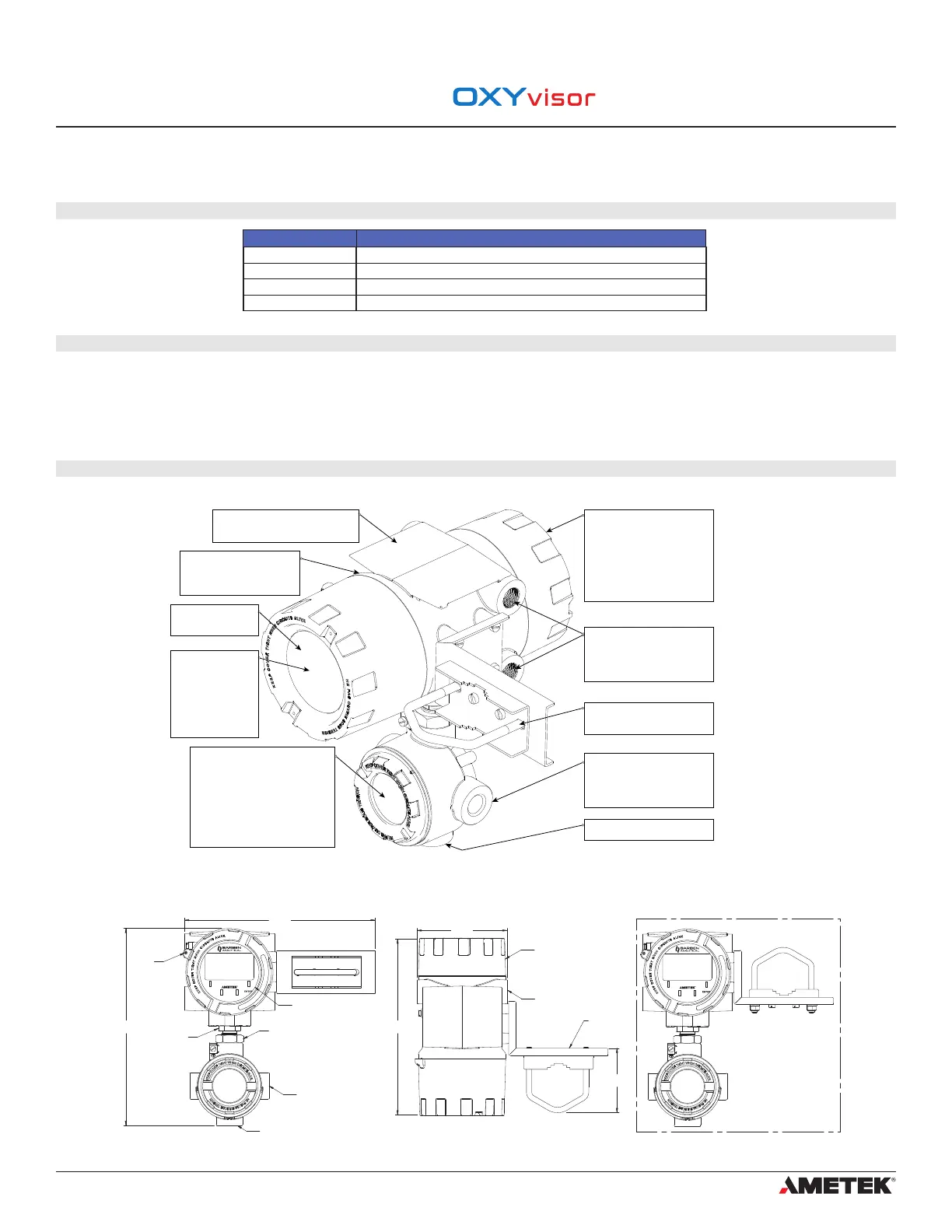
OXYvisor Analyzer Overview
Figure 1 - OXYvisor overview of hardware features
2�6 OXYvisor Analyzer Features (Hardware/Firmware/Soware)
OXYvisor Analyzer Dimensions
Figure 2 - OXYvisor Overall Dimensions
11.4"
288mm
DISPLAY AND THROUGH-
THE-GLASS TOUCH
KEYPAD
3/4" FNPT (X2)
or M25 x 1.5 6H
conduit entries
1/2" FNPT (X1)
11.7"
298mm
FIBER OPTIC
BUSHING
P/N B3907-1SFP
or B3907-2SFP
JAM NUT
(FOR J-BOX ROTATION)
2 mm
Hex Lock
ESC
OXYvisor
5.4"
136mm
10.5"
266mm
REAR WIRING
COMPARTMENT
2” MOUNT
BRACKET
B5008-1125
3.8"
97mm
ALTERNATE MOUNT STYLE
HORIZONTAL PIPE
ESC
OXYvisor
3/4" NPT (X4)
or M25 x 1.5 6H
conduit entries
FRONT VIEW TOP VIEW
FRONT VIEW
(ALTERNATE MOUNT)
Rear (Wiring) Compartment
Contains the connection
terminals for power and all I/O’s
except oxygen sensor. The cap
(cover) is threaded, sealed via
O-ring and secured with a set
screw. The features allow easy,
but controlled, access to wiring
terminals.
Conduit Entries
There are four 3/4” FNPT or
M25x1.5 6H conduit entries
(size selected during ordering)
for the Rear (Wiring) Compartment.
Conduit Entries (Junction Box)
There are two 3/4” FNPT or
M25x1.5 6H conduit entries
(size selected during ordering)
for the Junction Box
Nameplate / Label
Contains the part number, company
info, and the Hazardous Area Markings.
Pipe Mount Bracket
316 SS, 2” Pipe / Field Mounting
Bracket.
Oxygen Sensor Entry
1/2” FNPT for the Oxygen sensor
Flameproof glass (Ex d)
Protects the HMI, LCD
and other electronics.
Human Machine Interface
The HMI, located
behind the flameproof
glass, includes backlit
LCD and Through-the-
glass keypad for user
configuration and full
interactive use.
Junction Box
Contains easily accesible sensor
connection(s).
All analyzer models
SMA connector for optical O2 sensor
or optical fiber wand assembly.
All analyzer models except Zone 1
Molex connector for Pt1000 RTD
Rugged Industrial Enclosure
IP66 / NEMA4x, pressure die-
casting with yellow chromating
and chemically resistant paint.
Section 2
Technical Product Specication
 Loading...