122770 06 18-09-2007 23
Defective Power PCB If the 3 LED’s on the Power PCB are not lit,
measure the following voltages on the
terminals of CN3 with the Main PCB
connected.
11 (+) to 12 (-) U > 0,6V
17 (+) to 18 (-): U > 0,6V
19 (+) to 20 (-): U > 0,6V
15 (+) to 16 (-): U > 1,0V
The voltages will appear in pulses.
If these are below the limits change the
Main PCB, adjust and re-calibrate the
calibrator. If not, change and adjust the
Power PCB.
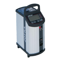
Error: Calibrator does not cool or heat sufficiently
(ATC-155 only).
Error message:
-
Likely cause: Solution:
Defective well
Set the SET temperature to –50°C.
On the power PCB measure the voltage
between CN8 terminal 1(+) and terminal 2(-
) and the voltage between CN1 terminal
1(+) and terminal 2(-).
If the voltage on CN1 is higher than 30V
replace the well and re-calibrate the unit.
If the voltage on CN8 is 0.45V ±0.01V and
the calibrator does not cool down
sufficiently, replace the well and re-calibrate
the unit.
Defective Power PCB If the voltage on CN1 is less than 30V and
the voltage on CN8 differs from 0.45V
±0.01V, adjust R9 until the voltage is 0.45V
±0.01V.
If it is impossible to adjust the voltage on
CN8, replace the Power PCB.
 Loading...


