26 18-09-2007 122770 06
Likely cause: Solution:
Defective Stirling
Controller PCB
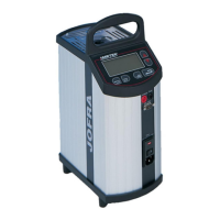
Measure potentials on CN103 Stirling Out.
Set Calibrator to –90°C
PIN1 Stirling Supply
PIN2 Stirling GND
PIN3 Stirling CTRL
PIN4 Stirling On/Off
PIN5 Stirling Alarm
PIN6 FPSC GND
Between PIN1 and PIN2 > 23V
Between PIN6 and PIN3 > 0,8V and < 5V
Between PIN6 and PIN4 = 0V
Between PIN6 and PIN5 < 30mV
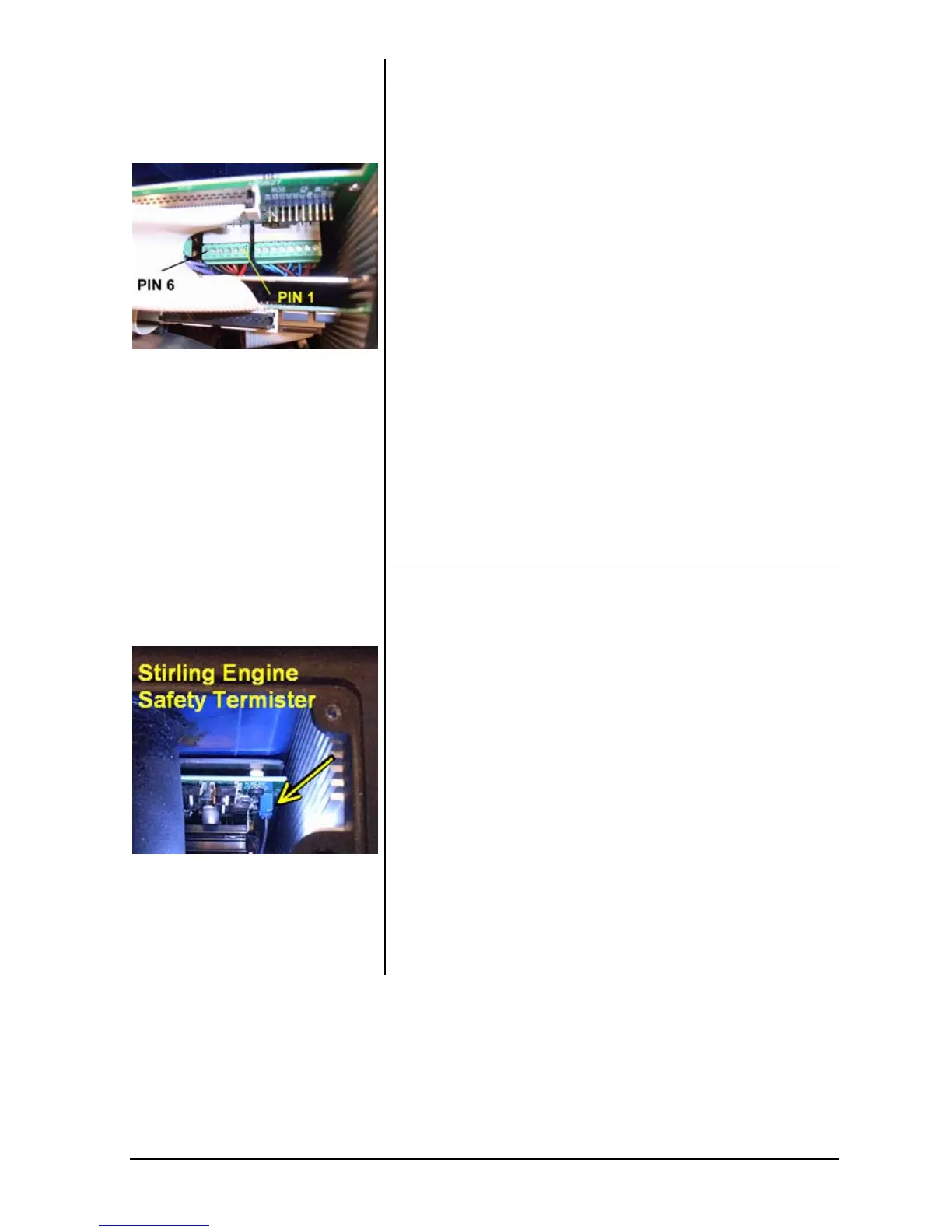
If the Stirling Alarm is
high
Pull out blue connecter on Stirling Controller
PCB and measure the resistance over the
Stirling engine safety termister.
@23°C R
termister
≈ 43Kohm
If broken, replace sensor else replace
Stirling Controller PCB.
NB! Before replacing sensor, contact
AMETEK Denmark’s Service Department
for guidance.
 Loading...


