EasyManuals Logo

Ametek JOFRA ATC-125 Service Manual

Ametek JOFRA ATC-125
89 pages
To Next Page IconTo Next Page
To Previous Page IconTo Previous Page
Page #41 background imageLoading...
Page #41 background image
122770 06 18-09-2007 41
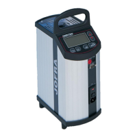
This picture shows an ATC-250 B.
This picture shows an ATC-125 B.
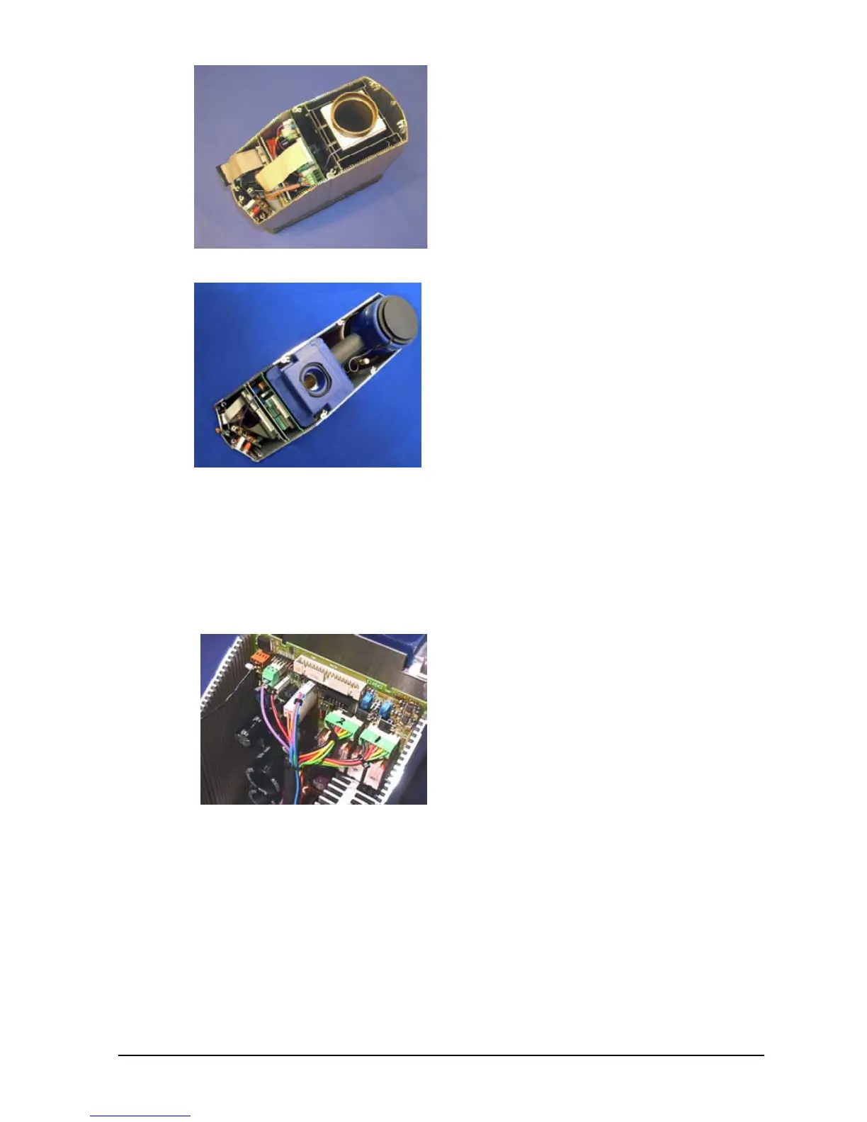
D. Removal of Power PCB
(Exploded views, pos. 7).
ATC-140/155/156/157 A/B
Mark the 2 connectors to the Peltier
elements with a pen as shown on
the picture, before disconnecting
the connectors on the Power PCB.
The numbers correspond to the
text on the PCB.
When reassembling the connectors
be careful not to mistake the wire to
the FAN (red and black) with the
wires to the stirring motor (red and
blue).

Other manuals for Ametek JOFRA ATC-125

Questions and Answers:

Question and Answer IconNeed help?

Do you have a question about the Ametek JOFRA ATC-125 and is the answer not in the manual?

Ametek JOFRA ATC-125 Specifications

General IconGeneral
BrandAmetek
ModelJOFRA ATC-125
CategoryMeasuring Instruments
LanguageEnglish

Related product manuals