52 18-09-2007 122770 06
The reference sensor is the one
placed in the right hole beneath in
the picture.
Disconnect the 2 sensor wires from
the Connection PCB.
When remounting a new sensor, it
must be placed in the hole together
with 0.5ml compound.
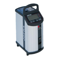
ATC-320/650 A/B:
Place the well unit upside down
with the wires pointing towards you.
The reference sensor is the one
placed to the right.
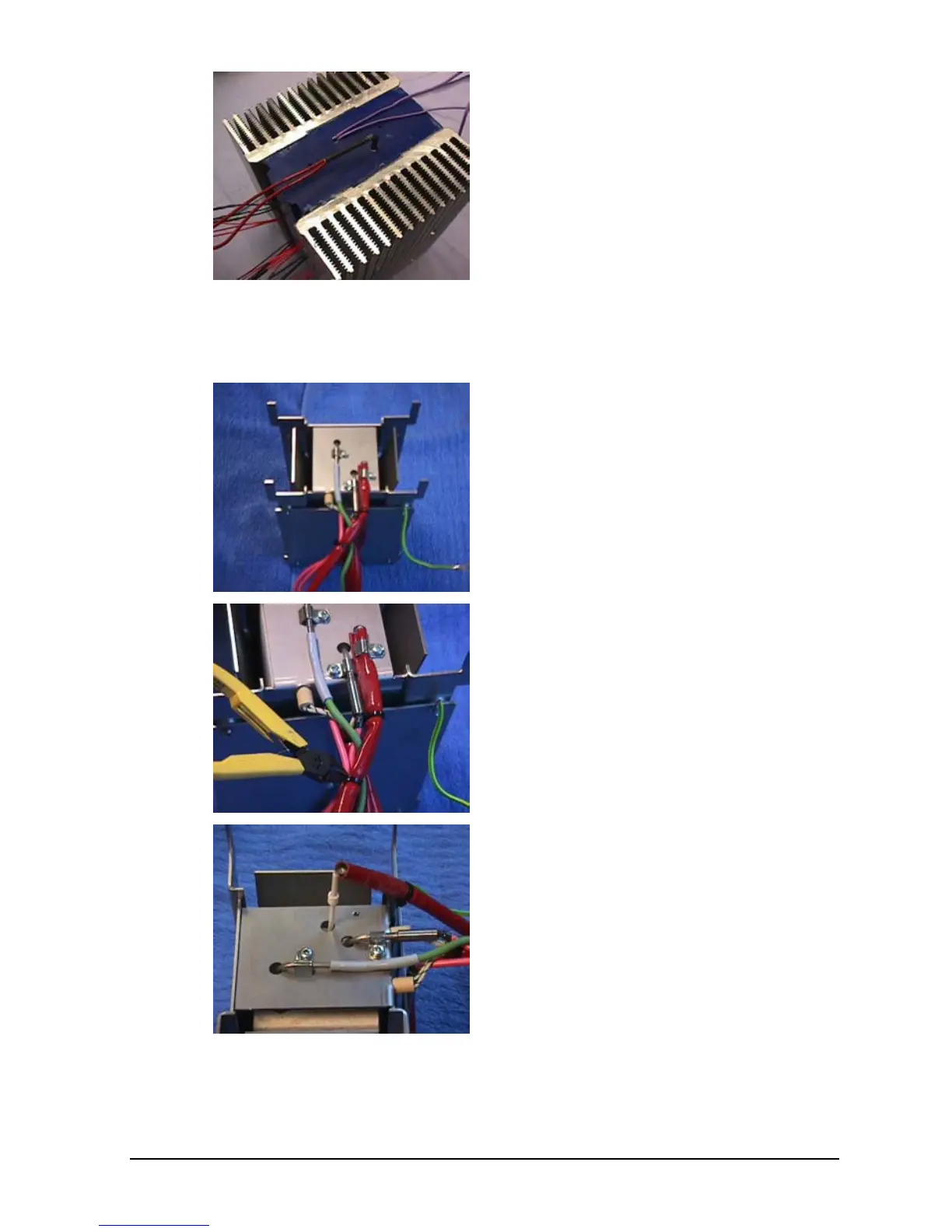
Cut the plastic strap holding
together the wires from the
reference sensor and the two
thermocouples with pink wires.
Note the position of the straps for
later assembly.
Remove the 3-mm screw, washer
and bracket holding the reference
sensor. Now it is possible to retract
the reference sensor from the unit.
 Loading...


