AMETEK CTs NetWave
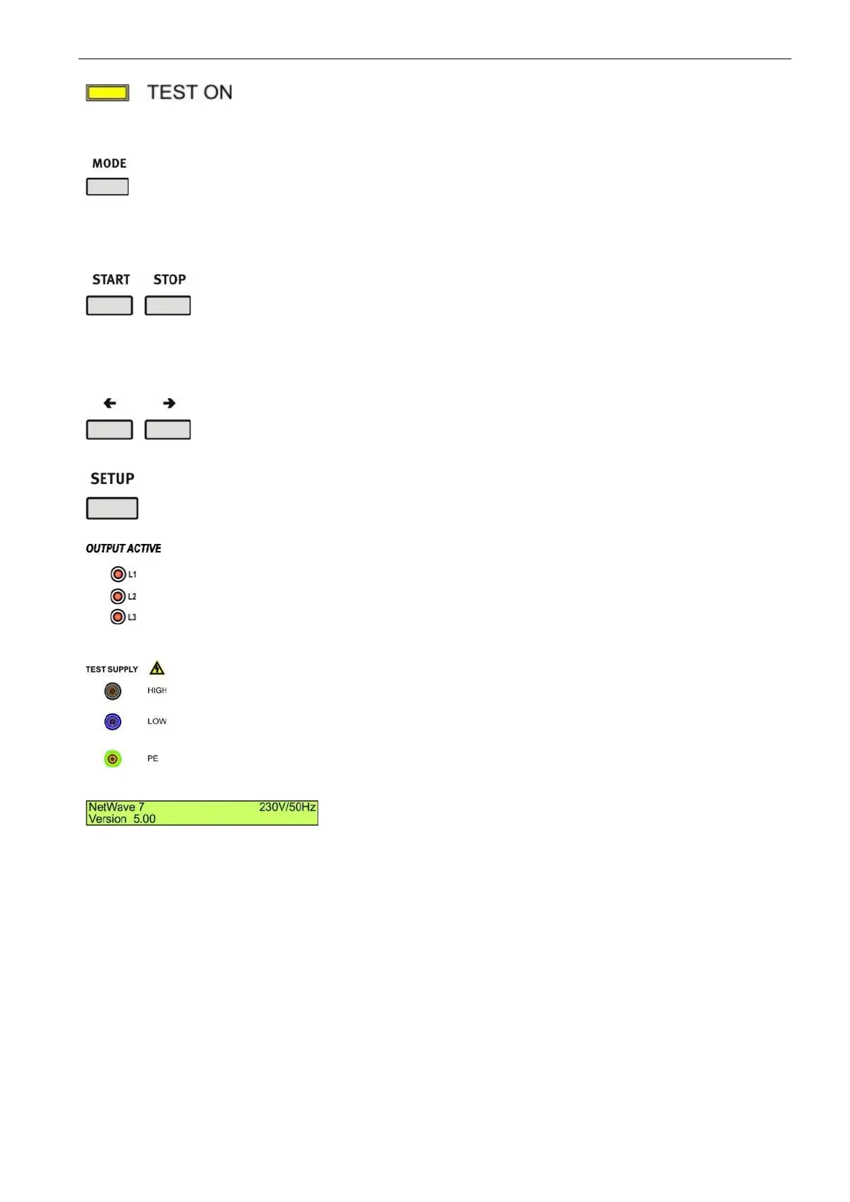
4. Test ON
Pressing this button will enable the output voltage
- TEST ON => LED is on
- TEST OFF => LED is off
Pressing this button will cyclic rotate the main menus.
- Wave Generator
- Measurement U / I
- Wave Manager
Start and Stop button for measuring and running
arbitrary waves.
START: Starts or continue.
STOP : Stops a measuring or a running arbitrary
waves.
2
nd
STOP : Exit of the play or setup change function
Cursor Key with the following function
- Scrolling in the menus
- Setting the values up / down
Menu button for the device configuration menu.
10. LED output active channel L1 to L3
LED display for indicate the active output channels.
Depends of extension 1 or 3 phase’s model.
L1: Single phase model.
L1, L2, L3: 3-phase model. Any other combinations are
possible with the 3-phase model
The test supply output to the EUT is located at the front
side and in parallel at the rear side.
Output Voltage:
AC up to 300 Vrms
DC up to 425 V
LCD display 2 x 40 characters
 Loading...