AMETEK CTs NetWave
4.2. 1-ph systems
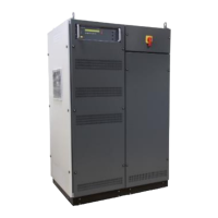
4.2.1. Rear view NetWave 3 / 3.1 / 5 / 7 / 7.1 / 7.2
The upper part of the NetWave is the control part. The control plugs are at the rear side of the NetWave
available.
1 Ventilator controller part
2 Framebus IN / OUT
3 Serial from DPA 500N / 503
4 Trigger IN1 / IN2
5 Trigger OUT1 / OUT2
6 Ethernet port
7 USB port
8 DUT monitor
9 GPIB / IEEE 488 port
10 Heat Sink air output
11 Ventilator ( output)
12 Safety circuit
13 Fuse 3.15 A slow blow ( ctrl)
14 Mains in CEE 32 A 3x400 V
15 Sense input
16 Test supply output
Ventilator for the controller Part
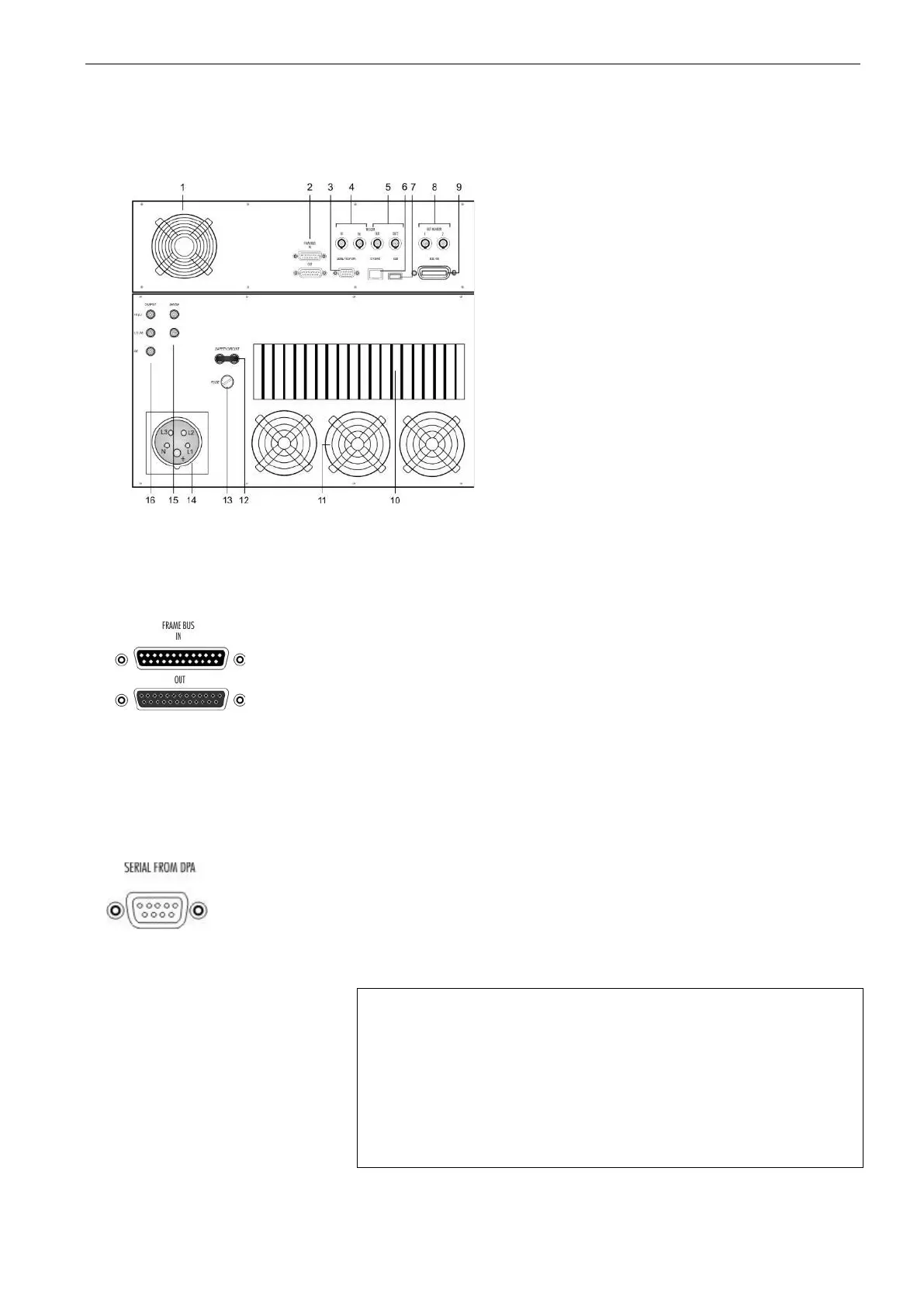
Framebus connectors.
Sub D 15 poles male and female
This port is used as communication and control bus
between EM Test devices.
Framebus terminating
In general, the framebus is terminated with a 120 Ω
terminating resistor between Pin 1 and Pin 9.
The frame bus termination can be orders under
ERP Number 101732
Serial connection to the DPA power analyzer.
Only legacy support of old DPAs, the port is no longer
used.
(RS 232 port, 9 pole Sub D male connector)
 Loading...