AMETEK CTs NetWave
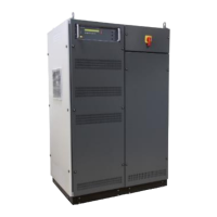
4.3.5. Rear view NetWave 90.x / 108.x
1 Recovery module (option)
2 Mains Supply input 3x400 V
3 Output panel for
- EUT power
- Sense
- Interlock
- Floating switch
4 Control output panel
- Control signals
- Trigger input
- Trigger output
- Interface
5 Output panel for
- EUT power parallel mode
4.3.6. Control Unit - Output Panel
1 Signal out (control)
2 Source in (control)
3 Trigger IN1/2
4 Trigger OUT 1/2
5 GPIB / IEEE 488 port
6 USB for data storage
7 Ethernet port
8 Serial from DPA 503
9 Framebus OUT
10 DUT monitor
11 USB 2 option measuring board
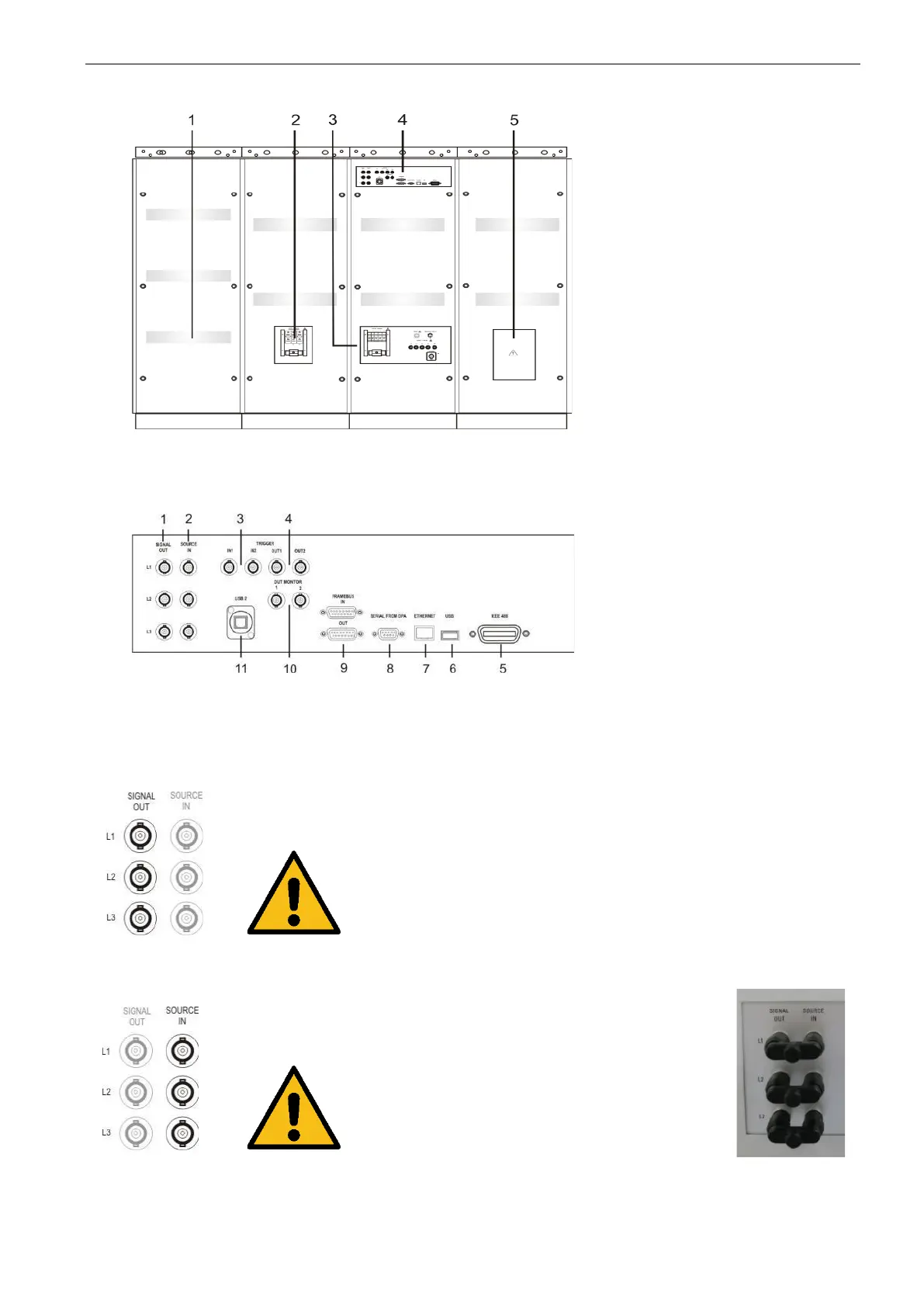
Analogue output signal for control the amplifier of the
NetWave phase L1, L2, L3.
The analogue signal has an output range of ± 10 V
For operating make sure that the cable bridge
between Signal OUT and Source IN is done
Analogue input to the amplifier of the NetWave phase
L1, L2, L3.
The analogue signal has an output range of ± 10 V
For operating make sure that the cable bridge
between Signal OUT and Source IN is done
 Loading...