EasyManua.ls Logo

Ametek NetWave 20 - Page 54

Ametek NetWave 20
140 pages
To Next Page IconTo Next Page
To Previous Page IconTo Previous Page
Loading...
AMETEK CTs NetWave
Rear side Fuse list
Number
Current [A]
Dimension [mm]
Type
Description
F1 - F3
315
Blade
NH1
General input line
F22 / F23
8
10x38
aM
Input Auxiliary Transformer
F24 / F25
15
5x20
WGT
Output Auxiliary Transformer
F26 / F27
6.3
5x20
WGT
NetWave Controller
F28
6.3
5x20
WGT
Auxiliary supply phase R neutral
F29
2.5
5x20
WGT
Auxiliary supply phase R phase
F30
2.5
5x20
WGT
Inverter phase R module 1
F31
2.5
5x20
WGT
Inverter phase R module 2
F32
6.3
5x20
WGT
Auxiliary supply phase S neutral
F33
2.5
5x20
WGT
Auxiliary supply phase S phase
F34
2.5
5x20
WGT
Inverter phase S module 1
F35
2.5
5x20
WGT
Inverter phase S module 2
F36
6.3
5x20
WGT
Auxiliary supply phase T neutral
F37
2.5
5x20
WGT
Auxiliary supply phase T phase1
F38
2.5
5x20
WGT
Inverter phase T module 1
F39
2.5
5x20
WGT
Inverter phase T module 2
F40 / F41
1
5x20
WGT
Safety Circuit
F42 / F43
Not used
5x20
Optional equipment
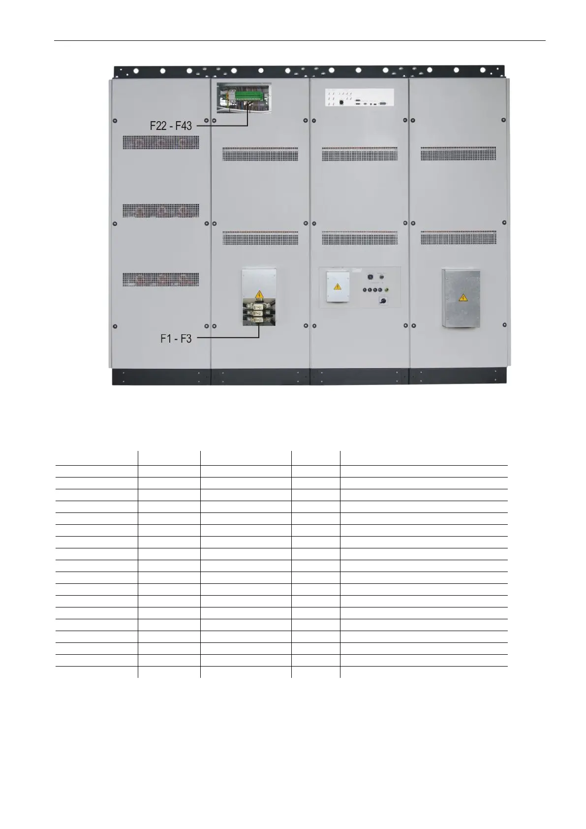
Note: The layout might slightly vary depending of the model.

Table of Contents

Related product manuals