AMETEK CTs NetWave
9.8. Filter Box L-BOX
The Filter box is mandatory to be used for tests “Voltage Distortion Spectrum” as per MIL-STD-704 LDC103 and
test condition C and K.
L-BOX 1-32
Application: 1-phase NetWave 7 and 3-ph NetWave up to 32
A
Voltage: AC :360 V, DC: 500 V
Current: 32 A
Frequency max. 60 Hz
Dimension (HxWxD) : 3 HU 154 x 448 x 500 mm
Weight: approx. 15 kg
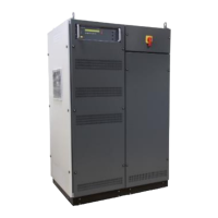
L-BOX 1-100
Application: 3-phase NetWave all models
Voltage: AC :360 V, DC: 500 V
Frequency max. 60 Hz
Current: 100 A
Temperature < 60 ºC internal
Dimension (HxWxD): 6 HU 289 x 448 x 500 mm
Weight: approx. 25 kg
Power 100 – 254 V
Fuse 2x 1 AT (slow blow)
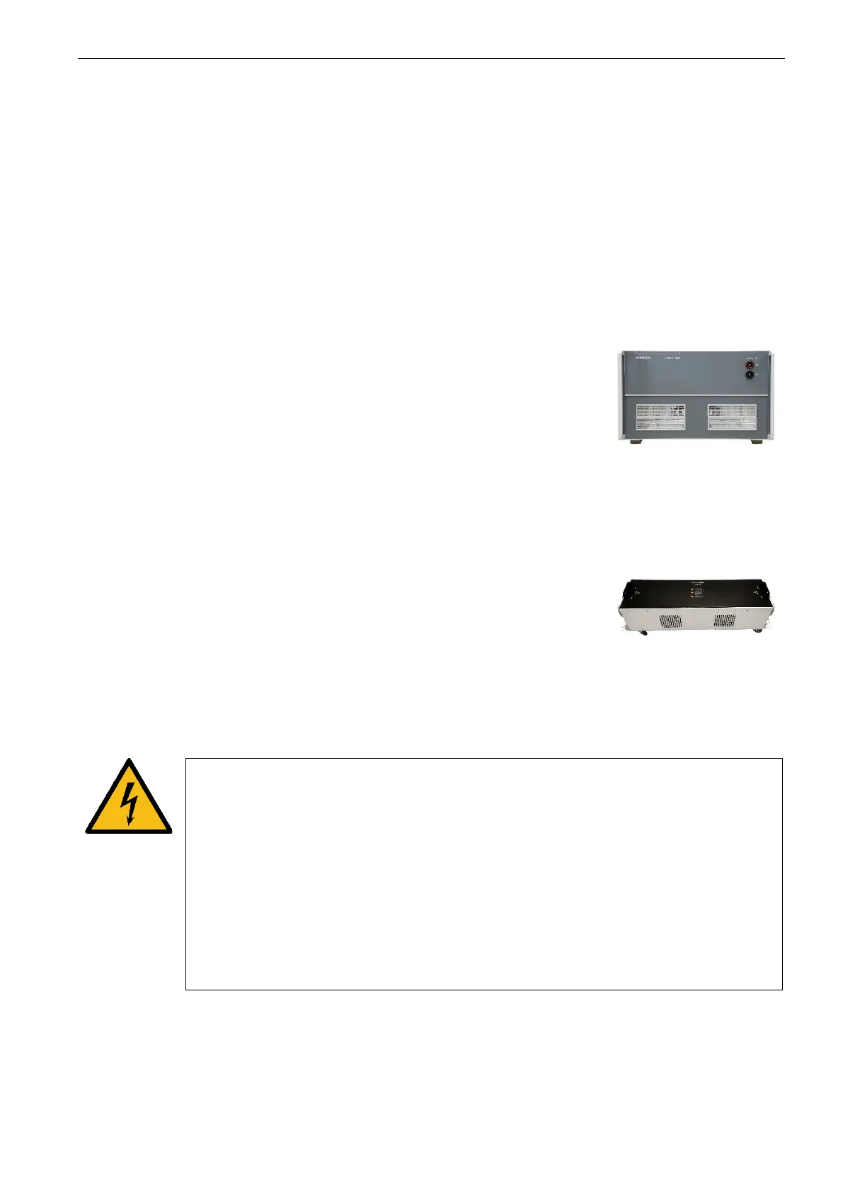
L-BOX 1-200
Application: 3-phase NetWave all models
Voltage: AC :400 V, DC: 560 V
Frequency max. 60 Hz
Current: 200 A
Temperature < 60 ºC internal
Dimension (L x W x H):810 x 270 x 230 mm
Weight: approx. 25 kg
Power 100 – 254 V
Fuse 2x 3.15 AT (slow blow)
First connect the device to protective earth by using the earth bolt on either side of
the device.
Switch off the voltage of the source before accessing the input or output terminals.
Use only the insulated allen key for tigheting or losing the screws of the terminal
blocks
Always switch on the fans before using the device.
 Loading...