AMETEK CTs NetWave
10.2. Interlock Feature
There are two versions of the interlock available that depend on the model and the serial number:
All models except xx.5: interlock that indicates the operating status, no control
xx.5 models: enhanced interlock with control and auxiliary contacts
NetWave 20 / 20.2 /
20.3, 30 / 30.2 / 30.3, 67
/ 67.2 / 67.3, 108.3
NetWave 20.5 / 30.5 /
67.5 / 108.5
10.2.1. Interlock Auxiliary (AUX)
The AUX interlock is a passive circuit that indicates the operating status of the source. It does not provide an
active output voltage, nor does it actively switch on or off the NetWave.
For each phase of the NetWave a separate power module is used. Each power module has a built-in monitoring
function. As soon as an internal failure is detected (i.e. overcurrent, over temperature etc.) the power module is
switched off. In parallel a relay contact is switched. This AUX interlock can be used to control external devices.
A typicall use case is a DC current breaker for electrical vehicle or inverter testing.
For each phase a relays switch is available to indicate the operating condition:
Power module is switched off because of internal
failure (i.e. overtemperature) or switch-off signal
received from control unit.
Normal operating mode at power on.
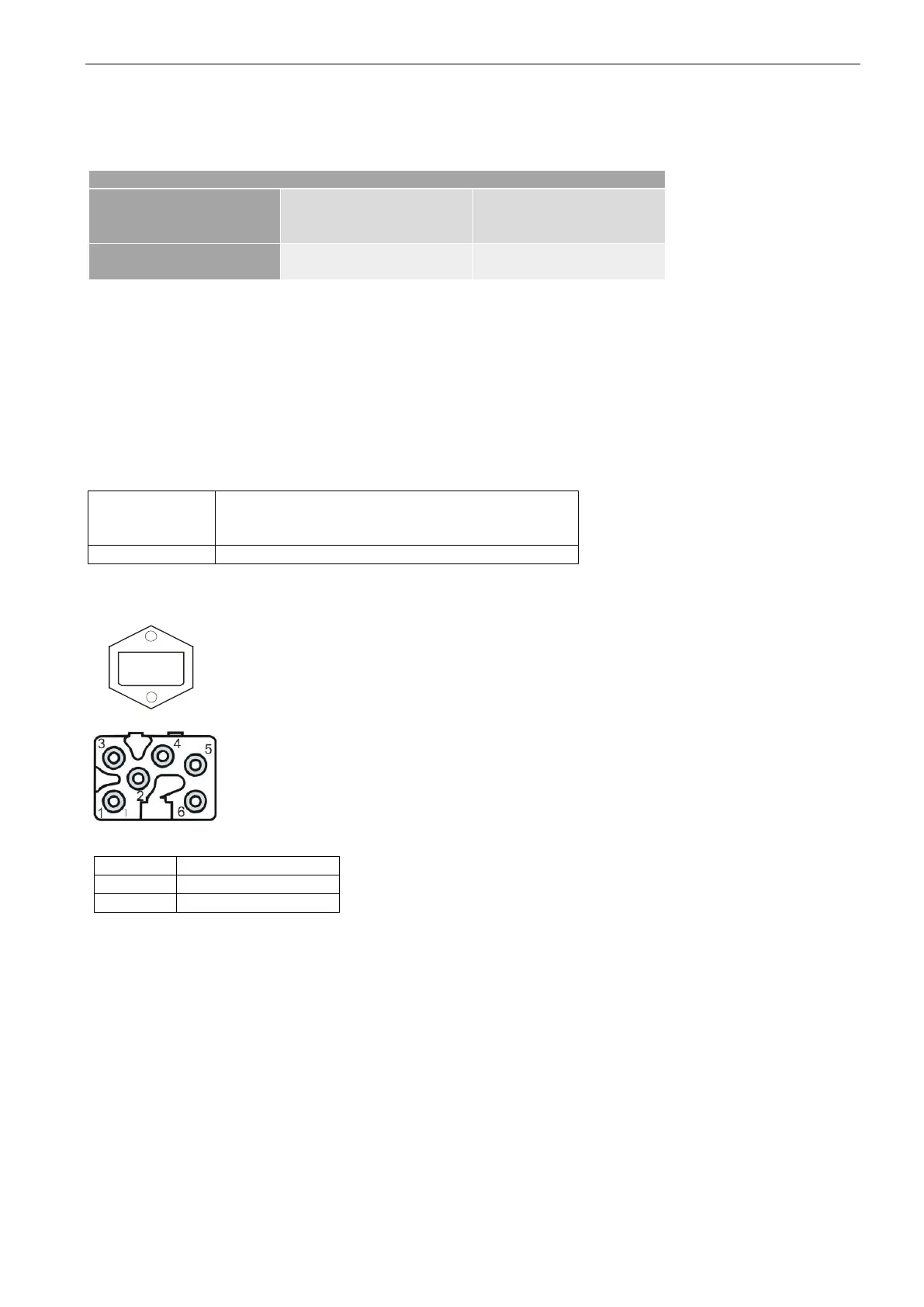
Receptable
Hirschmann STAKEI 5
Matching Connector:
Hirschmann STAS 5
Relays Type : Finder 55 series, model 55.32
Max. AC : 250 V / 10 A
Max. DC : 250 V / 10 A
State : NO (normally open)
Possible use of the interlock switch is:
- Control of an external circuit breaker to switch off the voltage at
the output, input or both
-
Possible wiring diagram for external circuit breaker
Certain applications require an external circuit breaker, i.e. to protect the NetWave from kickback voltages
(inverter testing).
Wiring diagram:
 Loading...