AMETEK CTs NetWave
Note: see above for power ratings of relay contacts.
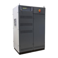
10.2.2. Interlock CONTROL
NetWave models with the CONTROL interlock feature offer additional interlock functionalities. It allows to
actively control the output switch of the NetWave. It also includes two relay contacts that indicate the status of
the switch.
All NetWave with interlock CONTROL also include the interlock AUX connectors (see above).
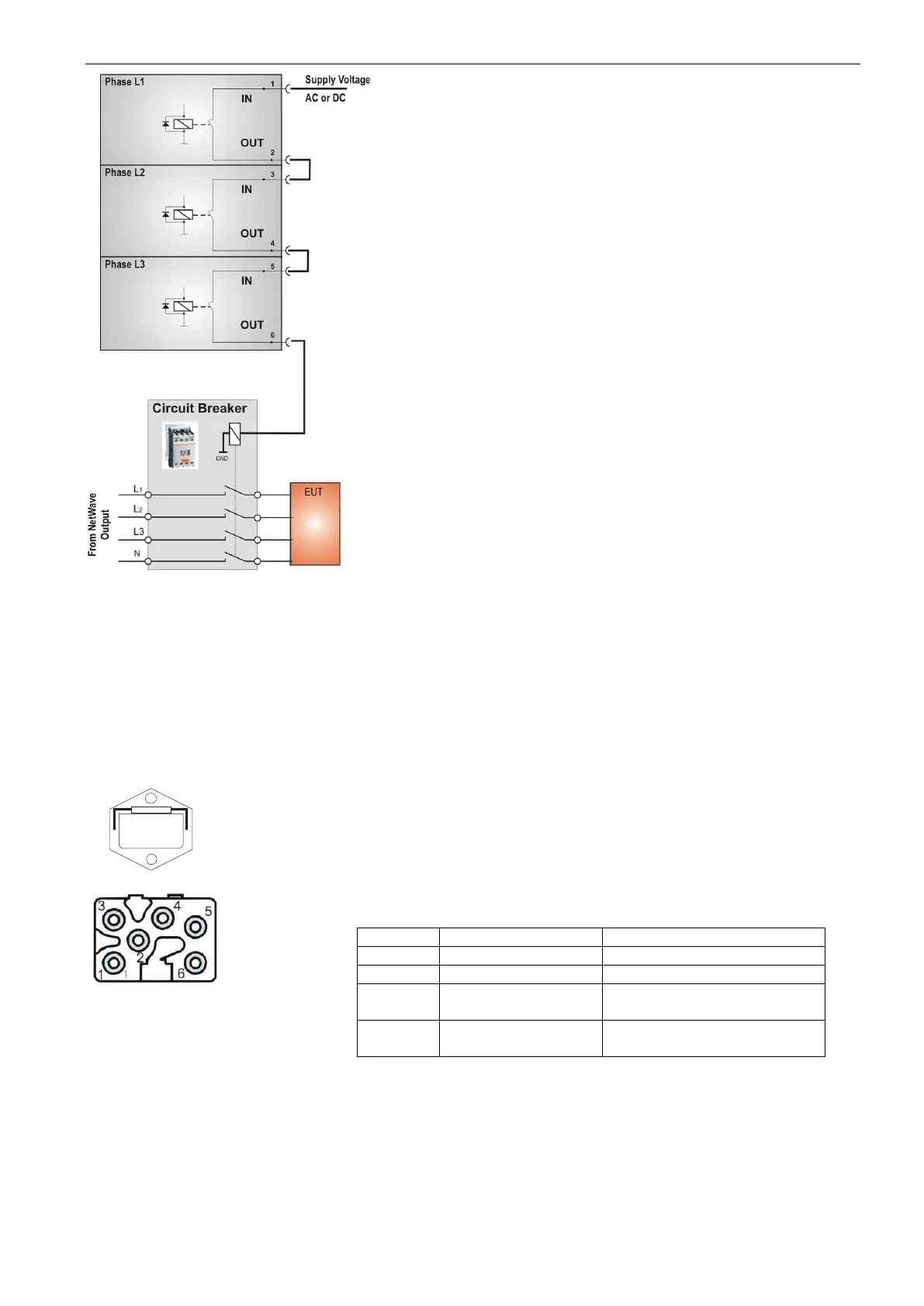
Connector Details CONTROL
Pin 1 provides a 24 VAC supply
Pin 2 is the control line of the NetWave output relay
Pin 3 and 4 are the contacts of the first indicator relay (normaly open)
Pin 5 and 6 are the contacts of the second indicator relay (normally
closed).
The two relays operate inversely.
 Loading...