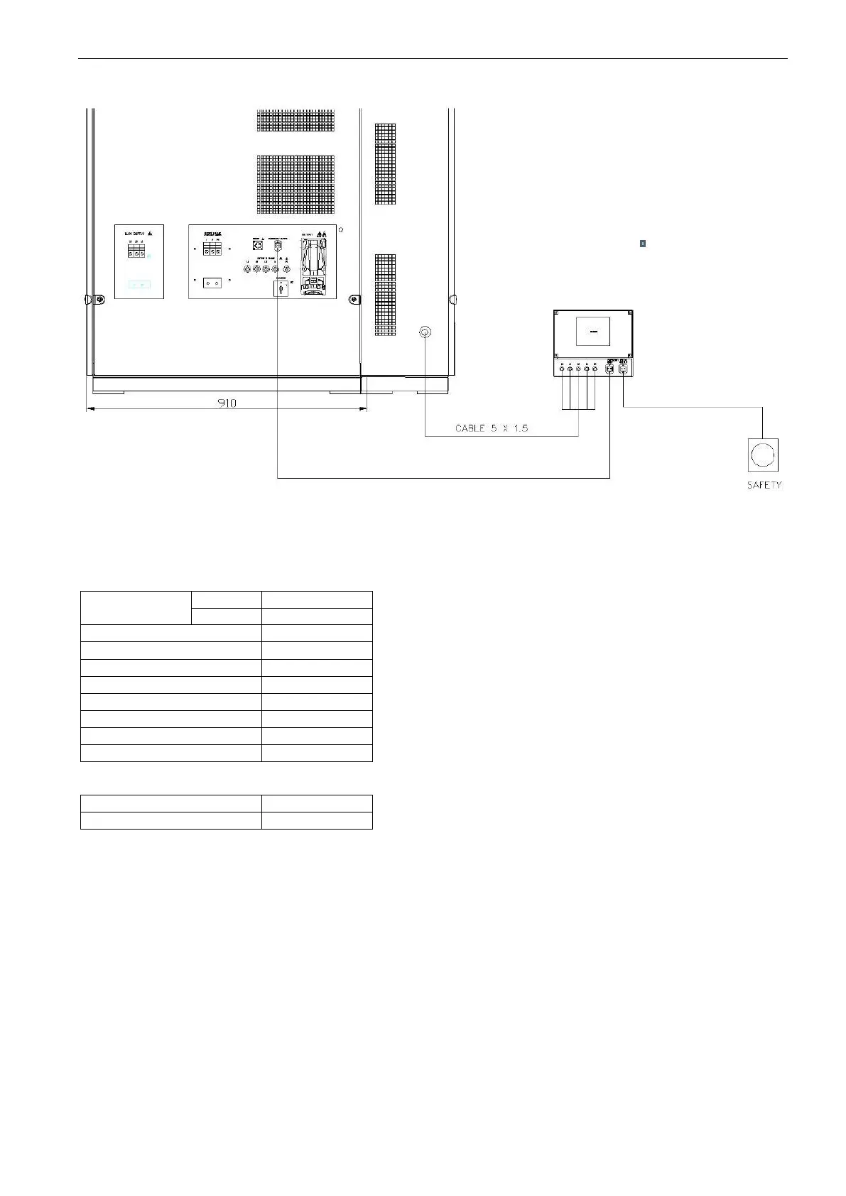
EasyManua.ls Logo

Ametek NetWave 3.1 - Page 120

Ametek NetWave 3.1
140 pages
To Next Page IconTo Next Page
To Previous Page IconTo Previous Page
Loading...
AMETEK CTs NetWave
Wiring diagram
Wiring:
- Interconnection cable from NetWave to IMD, 5 wires (L1, L2, L3, N, PE)
- Emergency switch interconnection cable from NetWave to IMD
- Emergency switch button with cable connected to IMD
The IMD is tested and delivered with these standard settings:
Alarm
Limit 1
10 k
Limit 2
1 k
Memory
ON
DC
None
Profile
Power Circuits
System
3AC
Coupling
None
Device
Active
Tstart
0
Input monitor
Off
Typical values
TEST ON switched off
80 k
TEST ON switched on
64 k

Table of Contents

Related product manuals