PARSTAT 4000 Hardware Manual
PARSTAT 4000 Hardware Manual 10
2. SAFETY AND COMPONENT PLACEMENT
This chapter lists safety precautions for use when operating the PARSTAT 4000; please
read them. There are suggestions for system component placement and information on
possible RF interference and transient sensitivity.
2.1. Safety Considerations
2.1.1. Line Voltage Settings and Fuses
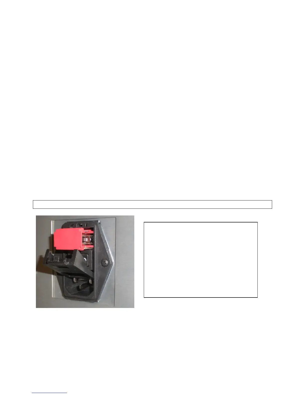
The PARSTAT 4000 has a Corcom™ Power Entry Module on the left side of the rear
panel. The Corcom module (pictured below) contains the power connector and two line
fuses. The PARSTAT 4000 automatically detects the correct line voltage and
frequency, so there is no line voltage changes required in the Corcom.
The PARSTAT 4000 is supplied with the line voltage fuses in place, as well as extra
fuses supplied with each unit. For fuse replacement:
For 100 – 120 Vac line voltages, use a 8.0 A T (slow-blow) fuse (Littlefuse® type
213, 5 x 20 mm or equivalent).
For 220 - 240 Vac line voltages, use a 4.0 A T (slow-blow) fuse (Littlefuse® type
213, 5 x 20 mm or equivalent).
Caution: Do not use makeshift fuses or short-circuit the fuse holders
NOTE: The PARSTAT 4000 requires
20s between power-off and power-
on. If the main power switch is
cycled off-on shorter than this 20s
duration, the main voltages to the
electronics will not be applied, and
the system will not power up
properly. This delay enhances the
overall reliability of the internal
power supply and the system as a
whole.

 Loading...

