PARSTAT 4000 Hardware Manual
PARSTAT 4000 Hardware Manual 15
3. INSTALLATION
This chapter describes the PARSTAT 4000 connectors and indicators and details how to
connect it to the host PC, electrochemical cell, and other equipment you might wish to
use with it. The pinouts for AUXILIARY INTERFACE connector and cell cable connector
are listed in Sections 4.4. and 4.5., respectively.
3.1. Enabling the USB port on your PC
Some PC manufacturers ship their PCs with the USB port disabled. Check for this before
trying to use the PARSTAT 4000. If the port is disabled, follow the manufacturer’s
instructions for enabling it.
3.2. Connectors and Indicators
3.2.1. Rear Panel
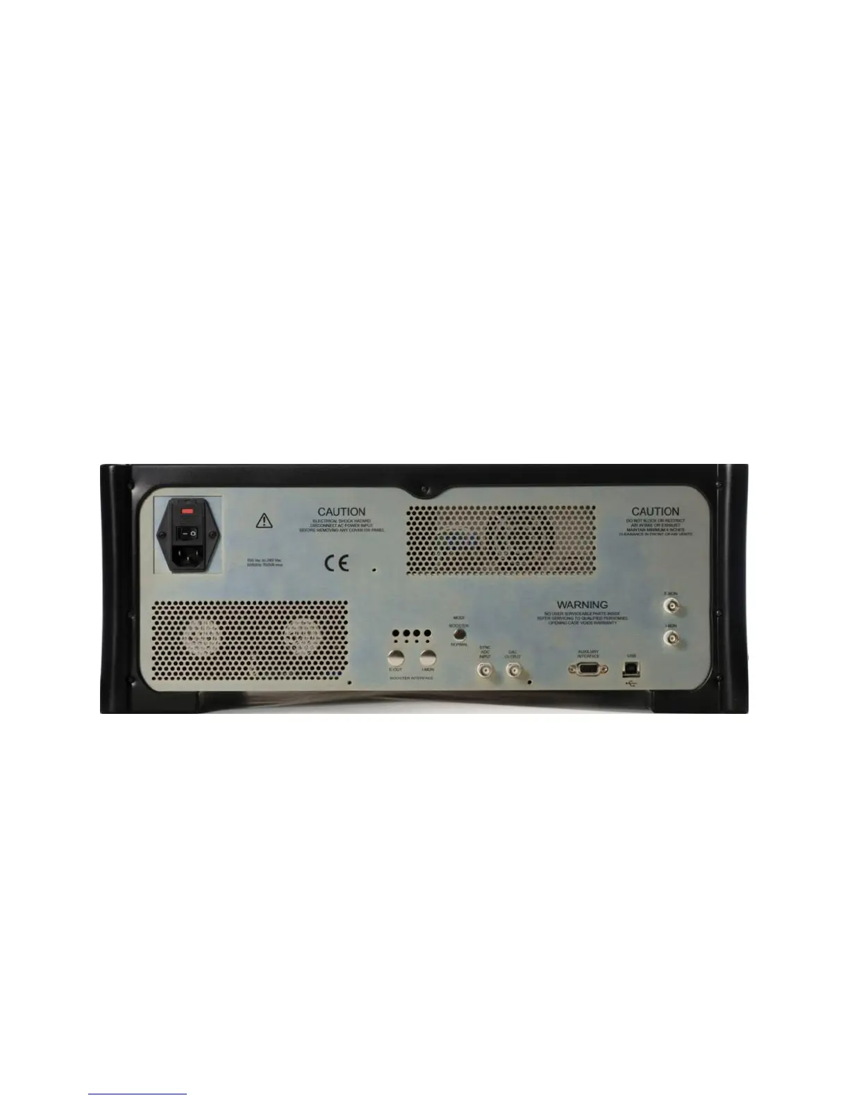
The PARSTAT 4000 rear panel is shown in Figure 4.
FIGURE 4. PARSTAT 4000 Rear Panel
3.2.1.1. INPUT POWER
120-240-V; the supplied AC power cord can be connected to 120-
240V AC.
3.2.1.2. USB
Attach the supplied USB cable to this connector and to the USB
connector on the PC. You can connect to and disconnect from the
PC without shutting down or restarting Windows or VersaStudio.

 Loading...

