PARSTAT 4000 Hardware Manual
PARSTAT 4000 Hardware Manual 7
-
+
WORKING
I OUT
I OUT
I/E CONVERTER
CURRENT RANGES (EXAMPLE)
2 mA
200 uA
20 uA
2 uA
200 nA
20 nA
E IN
E IN
-
+
POWER AMP
Cell Switch
COUNTER
SINGLE ENDED
-
+
REFERENCE
SENSE
E OUT
E OUT
DIFFERENTIAL
ELECTROMETER
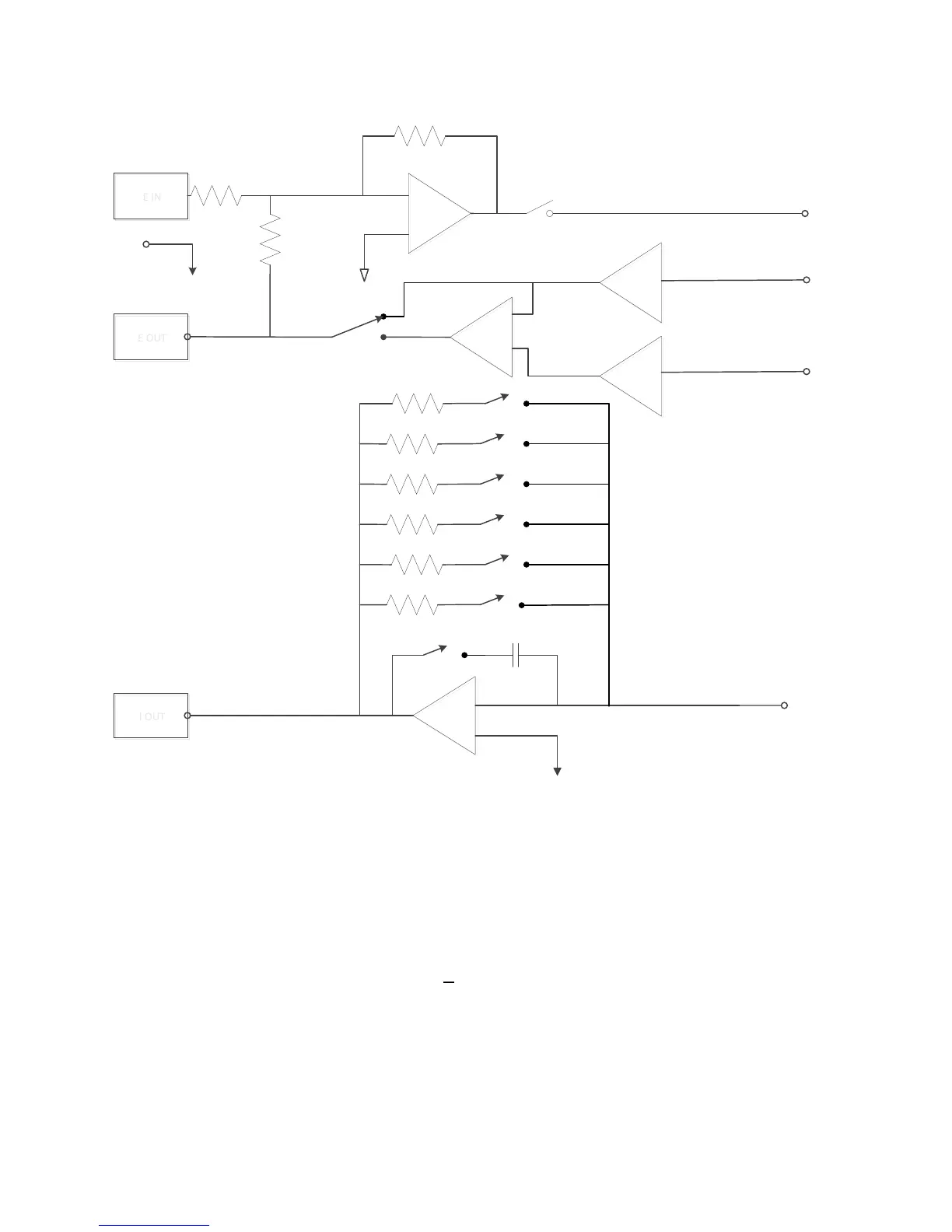
Figure 2. Potentiostat-Mode Block Diagram
1.2.2. Galvanostatic mode
In galvanostatic operation, the PARSTAT 4000 controls the current between the counter
and working electrodes at the specified fraction of the selected current range (up to the
maximum of the current range; see Figure 2). The counter electrode is driven to the
potential required (consistent with the + 48 V compliance of the control amplifier) to
establish the desired cell current. The reference electrode is not used in the control loop,
but is usually used to measure the potential at some point in the electrochemical cell
relative to the working-sense connection point.
 Loading...


