PARSTAT 4000 Hardware Manual
PARSTAT 4000 Hardware Manual 21
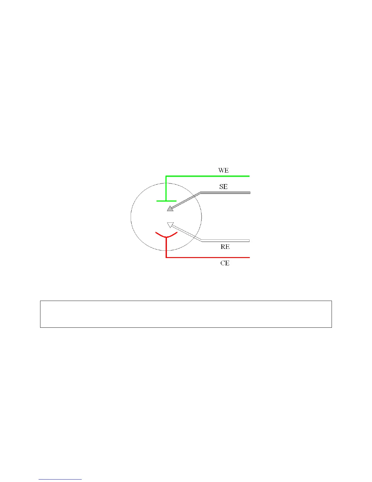
Figure 7. Three-Electrode Connection
c) There are some applications for which a four-terminal (Figure 8) connection
is required. In this case, the potential between the reference and sense are
controlled and measured. This can be a 4-terminal connection to a low
impedance battery or capacitor, or the Sense electrode can be an additional
reference electrode (for instance, in controlling the potential across a
membrane in a H-cell setup).
Note: Running experiments in this mode requires that the Electrometer
Mode setting in the software be set to Differential for the correct potential
to be applied and read.
Figure 8. Four-Electrode Connection
CAUTION: Take care that the leads do not accidentally short together. Because
the black ground lead is often unused, it tends to be overlooked and
is more likely to accidentally short together with another lead.
6. The polarity of the potential at the counter electrode will be opposite the “applied
potential”. This is necessary to establish the correct polarity relationship at the
working electrode versus the reference electrode.
7. After all other connections to the PARSTAT 4000 are complete, experiments can
be set up and performed.
 Loading...


