ABOUT
1. 3
BOARD INTERFACE
(See page 26 for
the optional CAN bus
interface)
fatbox G3
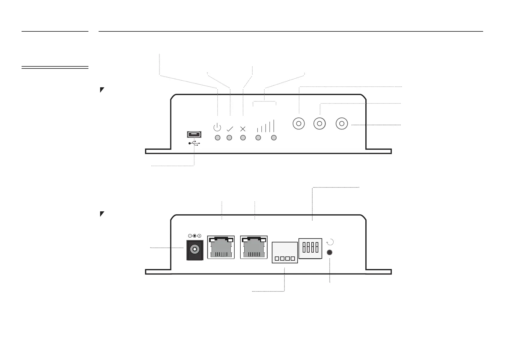
FRONT PLATE
BACK PLATE
cel l 1
signal
gps
cel l 2
amplied
engineering
fatbox G3
R
et h1dc et h0 serial
dip
1 2 3 4
TX RX IN GND
D- D+
amplied
engineering
fatbox G3
Power
Serial Input Port (4-way plug in terminal)
USB port
Antenna Port 2
GPS Antenna
Antenna Port 1
System Reset
Press <1 second, soft reset the
router
Press >5 seconds, will revert
parameters to Factory Default
This is a 4-way general purpose
switch available to user application
program. DIP #4 (right-most) is
dedicated as ‘TEST MODE’ * which
is activated when DIP #4 is in
‘OFF/down’ position during power
up.
*
During ‘TEST MODE’, after power up is
stable (e.g. 1 minute) a program will
monitor a switch (contact between #3
and #4 of Serial Input Port)
Press #1, if INPUT (#3 of Serial Input
Port) is working, LED ‘YES’ will blink
once
Press #2, with a ‘loop back’ wire
connected between #1(TX) and #2(RX)
of the Serial Input Port. The LED ‘YES’
will blink twice
Press #3, once a 3G/GPRS/EDGE
session is established, LED ‘YES’ will
blink three times
(Left to Right)
1 – TX output of serial port, MODBUS D-
2 – RX input of serial port, MODBUS D+
3 – INPUT, general purpose input port, switch to GND (pin 4) to
activate
4 – GND
LOW LED; HIGH LED
1,0 (<-95dBm) connection poor
0,1 (<-80dBm) connection medium
1,1 (>-80dBm) connection good
AUTOPING/
IPSEC/ Custom
Program
AUTOPING/
Custom Program
LED: POWER ON GENERIC ‘YES’ GENERIC ‘NO’ SIGNAL STRENGTH LEVEL
Main LAN Port ETH0
(default: 192.168.1.1)
Second LAN Port ETH1
(default: 10.1.1.1)
DIP Switch