AMSAFE SEATBELT AIRBAG SYSTEM
INSTALLATION, HANDLING AND SHIPPING INSTRUCTIONS E510629
SYSTEM DESCRIPTION AND OPERATION
02-Aug-2013
Page 5
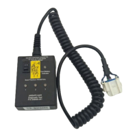
Figure 5: Inflator and Inflator Fittings
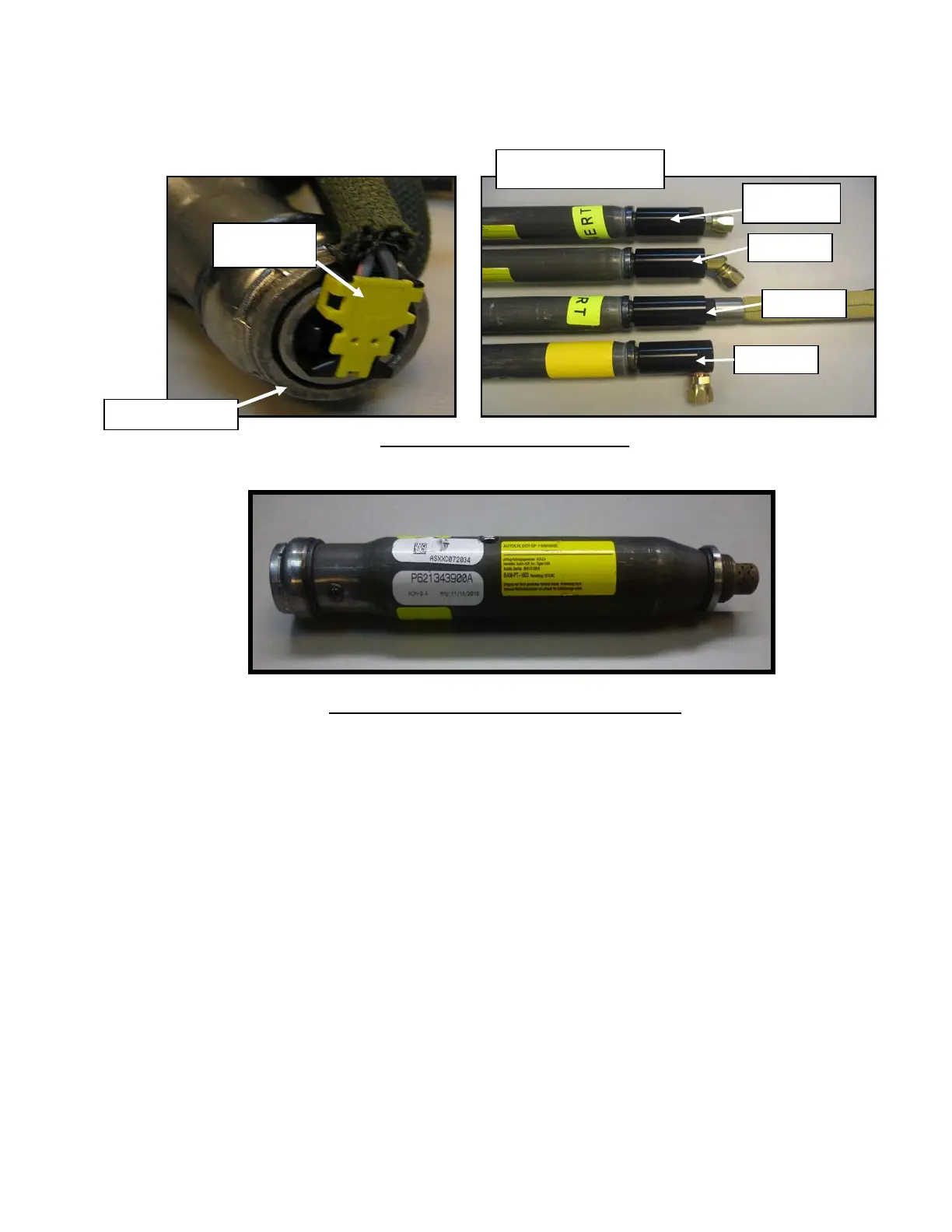
Figure 6: ACH 2.4 Inflator (no inflator fitting required)
(2) The Inflator provides inert helium-argon gas to inflate the airbag upon command from the EMA.
(3) Inflator assemblies are susceptible to rust in certain environments; this is considered a normal
condition for the Inflator. There is no requirement to remove or protect the Inflator from rust.
D. Cable Interface Assembly
(1) Enabling Switch System: The Cable Interface Assembly (Figure 7) connects the Inflatable Lap
Belt or Restraint Assembly or End-Release Buckle to the EMA. Cable lengths are unique to
each seat and dependent on the location of the EMA and Inflatable Lap Belt or Restraint
Assembly.
Non-Enabling Switch System: The Cable Interface Assembly connects to the EMA and Inflator
directly or by means of an extension/LRU cable.
(2) The Cable Interface Assembly attaches to the EMA via a connector located on the EMA pigtail
cable (Figure 7).
(3) A diagnostic connector is attached to a leg of the Cable Interface Assembly. This connector is
used to interface with the SDT.
Inflator Fitting to Inflator
Connection Point
90-degree
0-degree
0-degree
with swivel
45-degree
Inflator Front End
Squib
Connecto