AMSAFE SEATBELT AIRBAG SYSTEM
INSTALLATION, HANDLING AND SHIPPING INSTRUCTIONS E510629
SYSTEM DESCRIPTION AND OPERATION
02-Aug-2013
Page 6
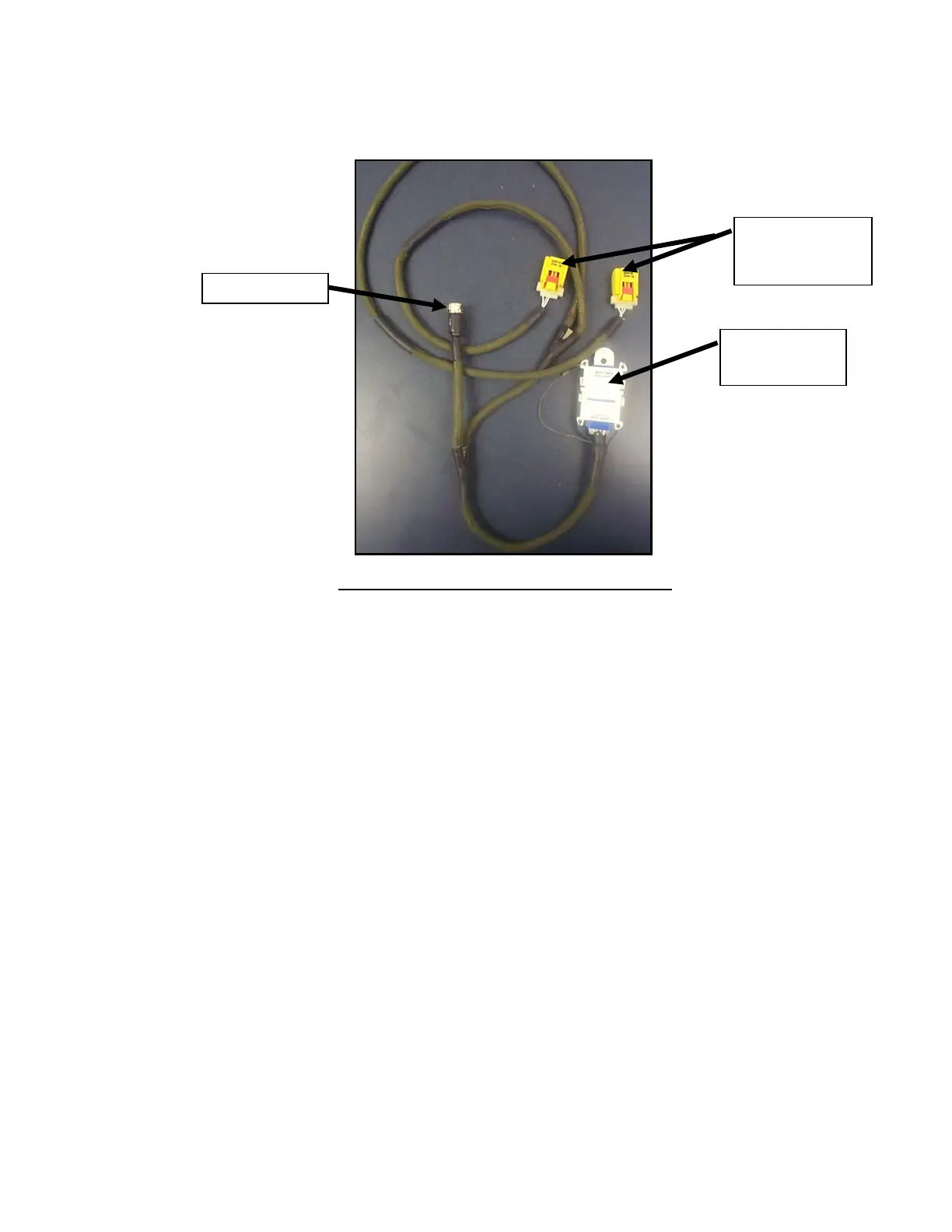
Figure 7: Cable Interface Assembly – Double Seat
E. EMA
(1) The EMA is a small box containing the system electronics, crash sensors, and battery (Figure
8). It should be mounted to hard seat structure to minimize vibration effects on the EMA and to
properly transmit the crash pulse to the EMA. The front of the EMA must face aircraft forward.
The EMA pigtail is located at the rear of the EMA.
(2) One EMA serves a single, double or triple seat assembly.
(3) The EMA Pigtail Cable has an electrical interface to the Cable Interface Assembly.
(4) The AmSafe Seatbelt Airbag System is designed to protect passengers during emergency
landing conditions. Proper deployment of the AmSafe Seatbelt Airbag requires the EMA to
recognize and deploy the Inflator at a predetermined deployment threshold. This threshold
does not allow inadvertent deployment during normal operations, such as hard landings,
luggage or food cart strikes on the seat, and random vibration or windmilling conditions.
(5) The AmSafe Seatbelt Airbag system EMA is battery operated. The EMA battery service life is
essentially defined by the refurbishment requirement of the EMA. Under typical operating and
environmental conditions, the battery service life is equal to the EMA refurbishment period.
The EMA battery is not user-replaceable. Refer to Table 1 for EMA refurbishment period.
Inflatable Lap Belt
/Restraint or
End-Release Buckle
Connectors
Diagnostic Tool
Connector and
Cover
EMA Connector