AMSAFE SEATBELT AIRBAG SYSTEM
INSTALLATION, HANDLING AND SHIPPING INSTRUCTIONS E510629
REMOVAL REPLACEMENT AND INSTALLATION PROCEDURES
02-Aug-2013
Page 3006
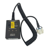
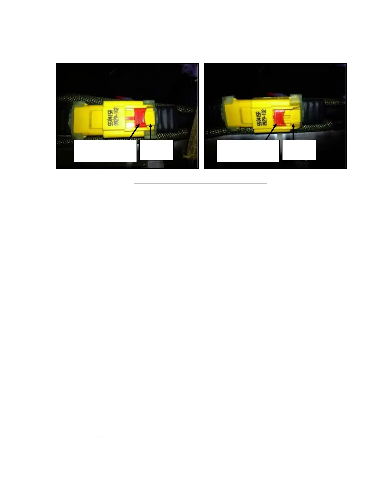
Figure 13: Inflatable Lap Belt Assembly Connector
(7) Remove Cable Interface Assembly from seat.
(8) Remove EMA from mounting brackets. Refer to seat OEM installation drawing for installation
details.
E. AmSafe Seatbelt Airbag V23 System Installation
(1) Remove the end cap plug (if new Inflatable Lap Belt Assembly) from Two-Point Airbag Belt
gas hose and discard. DO NOT REMOVE Safety Cable Tie on the airbag connector tongue at
this time (if installed).
CAUTION:
CHECK ORIENTATION OF TWO-POINT SEATBELT AIRBAG BELT(S)
BEFORE ROUTING GAS HOSE INTO INFLATOR FITTING. THE AIRBAG
COVER MUST PRESENT AWAY FROM OCCUPANT (WARNING LABEL
ORIENTATION IS ON INSIDE TOWARDS OCCUPANT).
(2) Route gas hose through seat per seat OEM installation drawing.
(3) Apply a thin, even coat of Loctite 242 thread locking compound onto the threaded end of the
Inflator before attaching to Inflator Fitting. If no Inflator Fitting, apply it onto the threaded end
of the gas hose barb before attaching it to the Inflator.
(4) Connect Inflator Fitting to Inflator (Figure 11B) or gas hose barb to Inflator using required in/lbs
torque (Ref. Table 4).
(5) Apply a thin, even coat of Loctite 242 thread locking compound onto the gas hose barb.
(6) Connect gas hose from Two-Point Airbag Belt(s) to Inflator Fitting (Figure 11B) using required
in/lbs torque (Ref. Table 4 for torque value). The Inflator Fitting connector fitting is a pressure
fitting which must be fully seated onto the gas hose barb for an air-tight fit.
(7) Attach Squib Connector(s) (Figure 11A) to Inflator(s). Orient connector as shown in Figure
11A and seat into front end of inflator until it locks in place.
NOTE
: DO NOT DAMAGE ANY PORTION OF SERIAL NUMBER ON INFLATOR WHEN
MOUNTING.
Red Locking Tab –
Unlocked Position
Yellow
Tab
Red Locking Tab –
Locked Position
Yellow
Tab