AMSAFE SEATBELT AIRBAG SYSTEM
INSTALLATION, HANDLING AND SHIPPING INSTRUCTIONS E510629
REMOVAL REPLACEMENT AND INSTALLATION PROCEDURES
02-Aug-2013
Page 3007
(8) Secure the Inflator and Inflator Fitting (if installed) onto the seat. Refer to seat OEM
installation drawing for mounting bracket details.
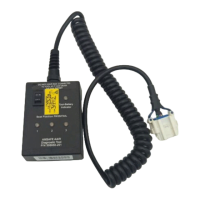
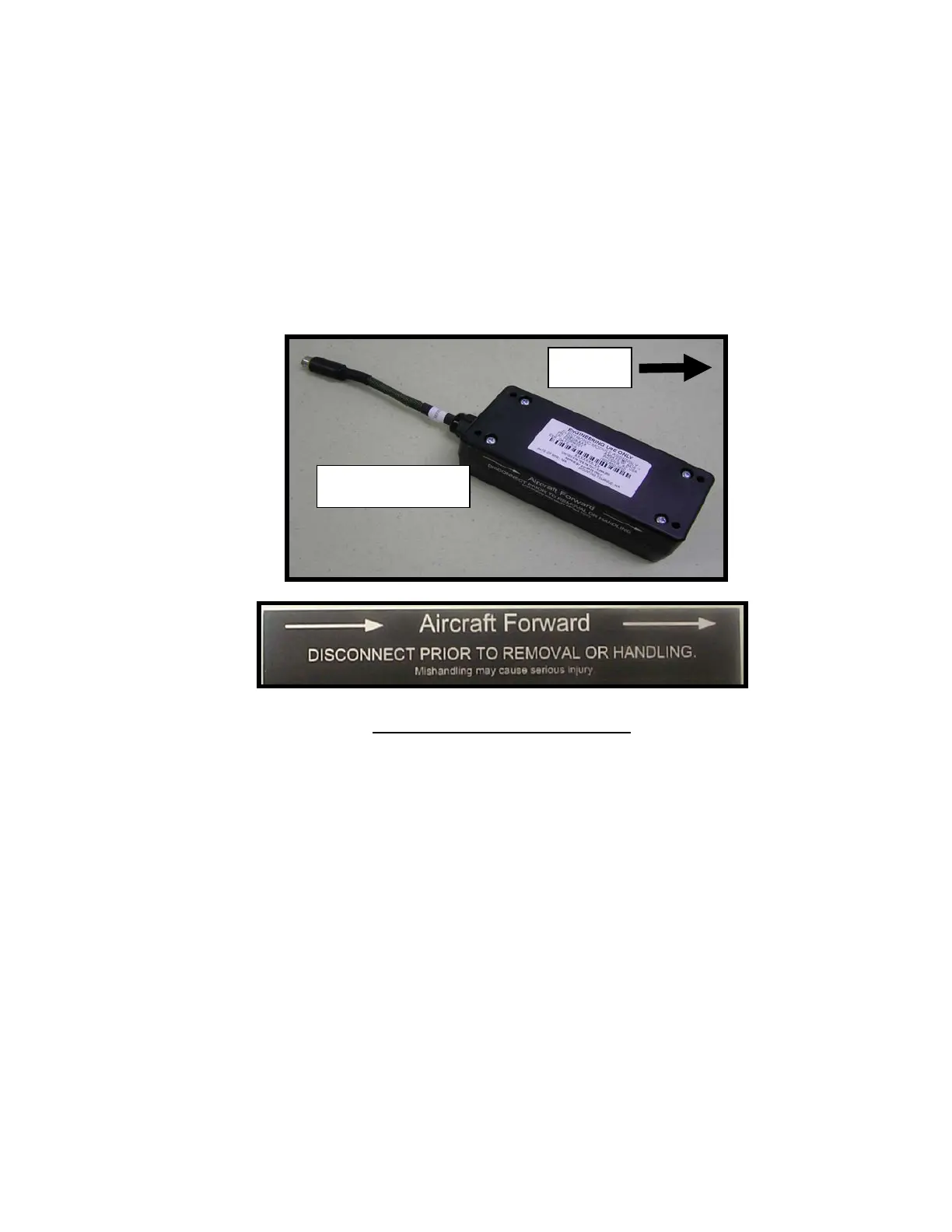
(9) Insert EMA into mounting hardware and secure. The arrow on the EMA label should face
aircraft forward (Figure 14). Refer to seat OEM installation drawing for mounting bracket
details and torque values, or reference Table 4 for torque values.
(10) Connect EMA to Cable Interface Assemblies EMA connector (Figures 1 and 2). The
connectors are keyed. Align connector halves and seat fully until they lock.
Figure 14: EMA Installation Orientation
(11) Install the Cable Interface Assembly per the seat OEM’s installation drawing and instructions.
(12) Connect Cable Interface Assembly connector(s) to Inflatable Lap Belt Assembly, Buckle
Assembly or extension cable connector(s). Connect mated halves together in proper
orientation and slide Red Locking Tab forward to locking position (Figure 13).
(13) Secure Two-Point Airbag Belt(s) to seat shackle.
(14) Connect the Buckle Belt to seat shackle.
(15) If installed, remove Safety Cable Tie from airbag buckle tongue before performing functional
testing.
(16) Perform functional test on system. Refer to Section 1000 – Testing and Fault Isolation for
testing procedures.
EMA Pigtail toward
rear of aircraft
Directional Label on Side of EMA
Aircraft
Forward