AMSAFE SEATBELT AIRBAG SYSTEM
INSTALLATION, HANDLING AND SHIPPING INSTRUCTIONS E510629
TESTING AND FAULT ISOLATION
02-Aug-2013
Page 1007
System without Enabling Switch:
WARNING:
IF THERE IS NO ELECTRICAL CABLE ATTACHED TO THE BUCKLE, THERE IS NO
ENABLING SWITCH, AND THE SYSTEM IS LIVE AS SOON AS ALL ELECTRICAL
CONNECTIONS ARE MADE.
(1) Use the following instructions to complete the AmSafe Seatbelt Airbag diagnostic check for a
system without an enabling switch.
(2) Check all possible electrical connectors within the AmSafe Seatbelt Airbag System. This
means check all Cable Interface Assembly connection ends: check EMA pigtail end and
connection(s) to all Inflator(s) for proper installation.
(3) Check EMA Pigtail, Cable Interface Assembly and Seat Belt electrical cable for breaks or worn
areas and replace, if necessary, before conducting test.
(4) When replacing SDT battery, do not allow debris or foreign objects in the opened battery
compartment.
WARNING:
THE AIRBAG SYSTEM SHOULD NEVER BE ACTIVE WITH AN UNSECURED SEAT OR
UNSECURED EMA. THE AMSAFE SEATBELT AIRBAG SYSTEM WILL
DEPLOY IF THE
EMA OR SEAT RECEIVES AN INPUT ABOVE THE DEPLOYMENT THRESHOLD OF THE
SYSTEM. THE DEPLOYMENT THRESHOLD IS EASILY ACHIEVED IF THE EMA IS
UNSECURED TO THE SEAT, OR IF AN UNSECURED SEAT RECEIVES A SHOCK SUCH
AS DROPPING THE SEAT ON THE FLOOR. IT IS VERY IMPORTANT THAT A SEAT WITH
AN ACTIVE AIRBAG SYSTEM (ALL CONNECTIONS MADE) IS SECURED SUCH THAT IT
CANNOT BE DROPPED OR MISHANDLED.
WARNING:
AN AIRBAG SYSTEM WITHOUT AN ENABLING SWITCH IS ALWAYS LIVE, EVEN WITH A
DISCONNECTED BUCKLE.
IF THE ENABLING SWITCH IS NOT PRESENT, THEN THE EMA MUST
NOT BE
CONNECTED TO THE CABLE INTERFACE ASSEMBLY UNLESS THE SYSTEM IS BEING
TESTED OR THE SEAT IS INSTALLED ON THE AIRCRAFT.
WARNING:
DISCONNECT THE SDT IMMEDIATELY AFTER THE DIAGNOSTIC TEST IS COMPLETE.
LEAVING THE SDT CONNECTED TO THE SYSTEM MAY RESULT IN DRAINING THE EMA
BATTERY.
ACTION RESPONSES FAULT DIAGNOSIS
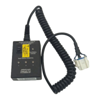
1
Turn SDT ON/OFF switch to ON. If
Battery check is OK, turn SDT OFF.
SDT Battery LED will illuminate green for
acceptable power and red for low battery
condition.
If red, remove cover on back of
SDT and replace with a new,
commercially available, 9-volt
battery.
2
Set Toggle Switch (# of Seats/Inflators)
to number of seats or inflators
connected to an EMA.
If a single restraint uses two inflators, set # of
Seats Toggle Switch to “2”
3
Connect SDT to Diagnostic Connector
on Cable Interface Assy. Turn SDT
ON/OFF switch to ON.
All System Validation LEDs are
green, go to Step 3.
All three System Validation LEDs will illuminate;
green for a “pass” condition or one or more
illuminate red for a “fail” condition.
If test fails, check all connections
and retest. Replace failed
component as indicated on the
SDT until a “pass” condition is met.
Retest after replacing each
component. Replace as follows:
- Battery LED – Replace EMA
- Sensor LED – Replace EMA
- Inflator LED – Replace inflator
cable, Inflator
If fail condition still exists, replace
Interface Cable