Start up Guide for Axpert-VT240S Series AC Drive
7
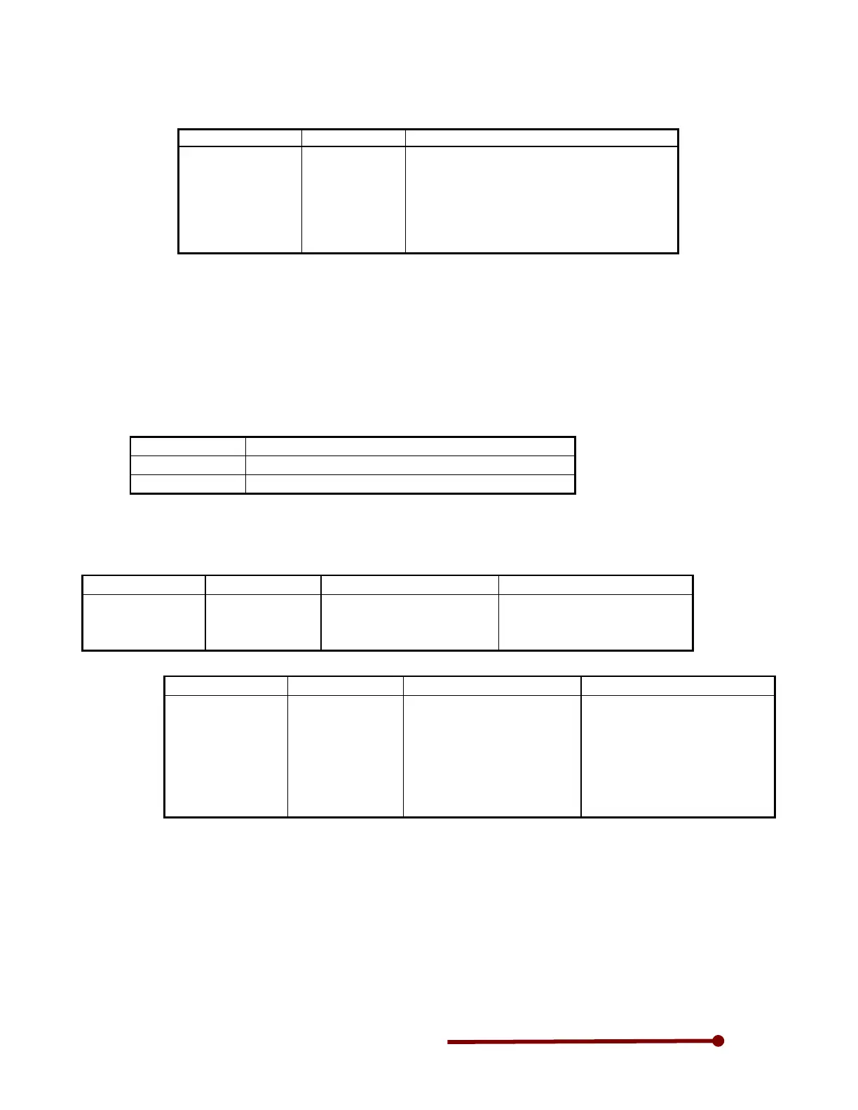
B00-4=60.00, B00-5=60.00, B00-6=15.0
Table 4-2-1
C30-0 = 11 or 21
B19-0 = 1, 2
B00-1
B00-2
B00-3
B00-4
B00-5
B00-6
Max/base frequency simple setting [Hz]
Motor rated output [kW]
Rated output voltage [V]
Maximum frequency (Note 1) [Hz]
Base frequency (Note 1) [Hz]
Motor rated current [A]
(Note 1)
The maximum frequency cannot be set below the base frequency, and the base frequency
cannot be set above the maximum frequency.
3-3 Automatic tuning & Test operation
Automatic tuning measures the constants of the connected motor, and automatically adjusts the
parameters so that the system is used to the fullest.
The VT240S automatic tuning function performs different measurements for each of the four control
modes. Carry out automatic tuning each time the motor being used or the applicable control mode is
changed. The automatic tuning mode is set with parameter B19-0 (automatic tuning selection). Refer
detail instruction manual for other control modes.
B19-0 Name
1 Simple adjustment mode for v/f control mode
2 High-function adjustment for v/f control mode
Automatic tuning will automatically change the parameters, so it is recommended to write down
the values set in Table 4-5-2 or Table 4-5-3.
Table 4-2-2
C30-0 = 11 or 21
B19-0 = 1
A03-0
B02-0, 1
Manual torque boost setting
DC brake voltage
R1: Primary resistance
The basic parameters, such as
boost voltage and brake voltage,
are adjusted without rotating the
Table 4-2-3
C30-0 = 11 or 21
B19-0 = 2
A02-2
A03-0
B02-0, 1
B02-4, 5
A02-5
A02-6
Manual torque boost setting
DC brake voltage
R1: Primary resistance
L
σ
: Leakage inductance
Slip compensation gain
Max. torque boost gain
The parameters related to the
slip compensation and max.
Torque
rotating the motor.
The magnetic saturation
characteristics are measured at
the voltage boost, and are
adjusted to match the max.