Amtech
2
Chapter-1: Installation Procedure
Always confirm the following points before turning ON the power after completing wire.
1. First, visually inspect the VFD
and ensure that the VFD has not been damaged in transport. If any
damage has occurred, do not energize the VFD, and contact the supplier.
2. Mount the VFD according to the detail Instruction Manual, Chapter 2 “Installation and Wiring”.
3. Be aware of the ambient temperature. Use the VFD within the specified ambient temperature
(50ºC).
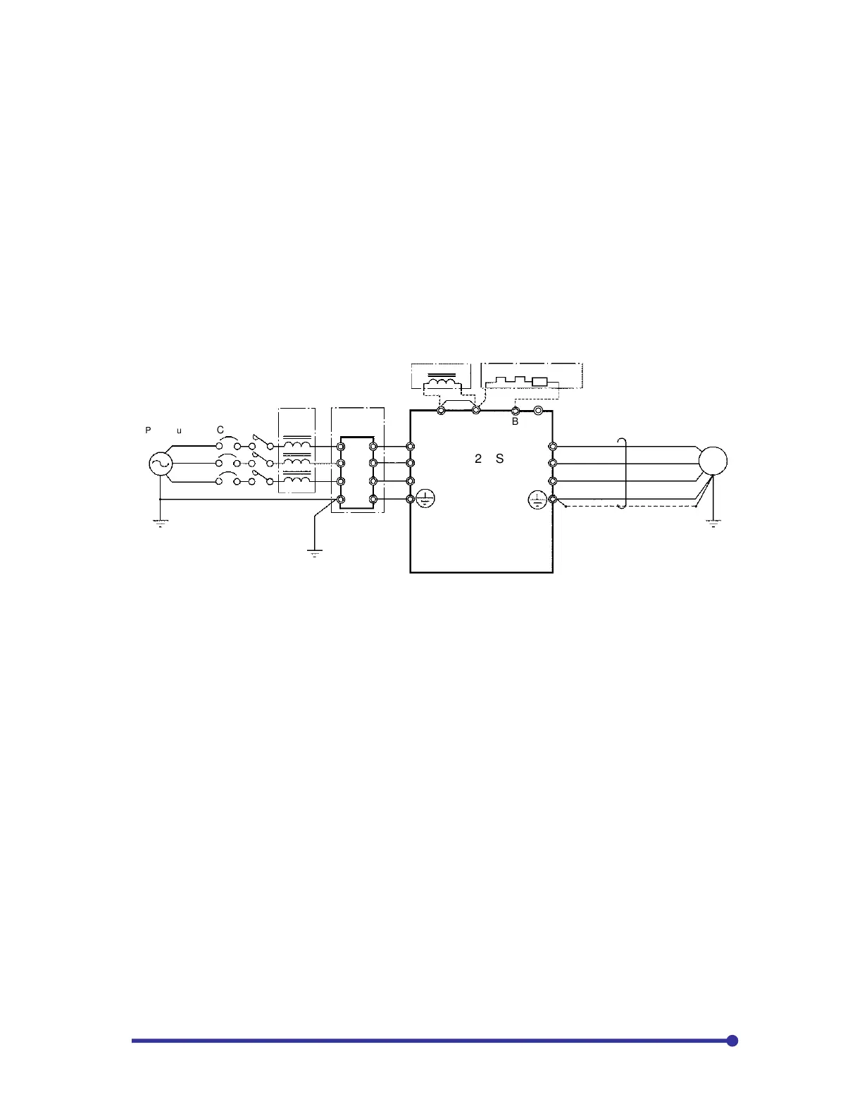
4. Connect the main circuit terminals L1, L2, L3 to the line side and terminals U, V, W to the motor side
as shown in Fig.1. Refer Chapter-2 of detail Instruction Manual for the terminal layout of other models.
Tighten the terminals with the specified torque as specified in Table-2-3, Chapter-2 of detail Instruction
manual for the Axpert-VT240S Series AC Drive. Make sure that none of the terminal section screws
are loose and there is no short circuit state in the terminals caused by wire scraps, etc.
2 5
3 6
E E
MCCB*
U
V
W
L1
L2
L3
(DCL)*
76D DB resistor*
Power supply
Line Reactor
DC Choke
Fig. 1 Example of main circuit wiring (018L, 022H and smaller)
(* Indicates optional equipment, refer detail IM for other models)
5. Connect the system ground to the ground terminal of the VFD.
6. Remove the coupling to the motor and machine, so that the machine can be run as a single unit.
7. With the 400V Series (075H or higher), there are some sections in the inverter, which operate with
an AC power supply, such as fan and magnetic contactor. In this case, set the power changeover
connector on the transformer auxiliary PCB according to the power voltage. If this connector is not
set correctly, the fan and magnetic contactor could burn.
380V: JP-380 440V: JP-440
400V: JP-400 460V: JP-460
415V: JP-415 480V: JP-480 (factory setting)
8. Make sure that the power supply is within the tolerable range.
9. Always correctly install the front cover and outer cover before turning the power ON.