Start up Guide for Axpert-VT240S Series AC Drive
17
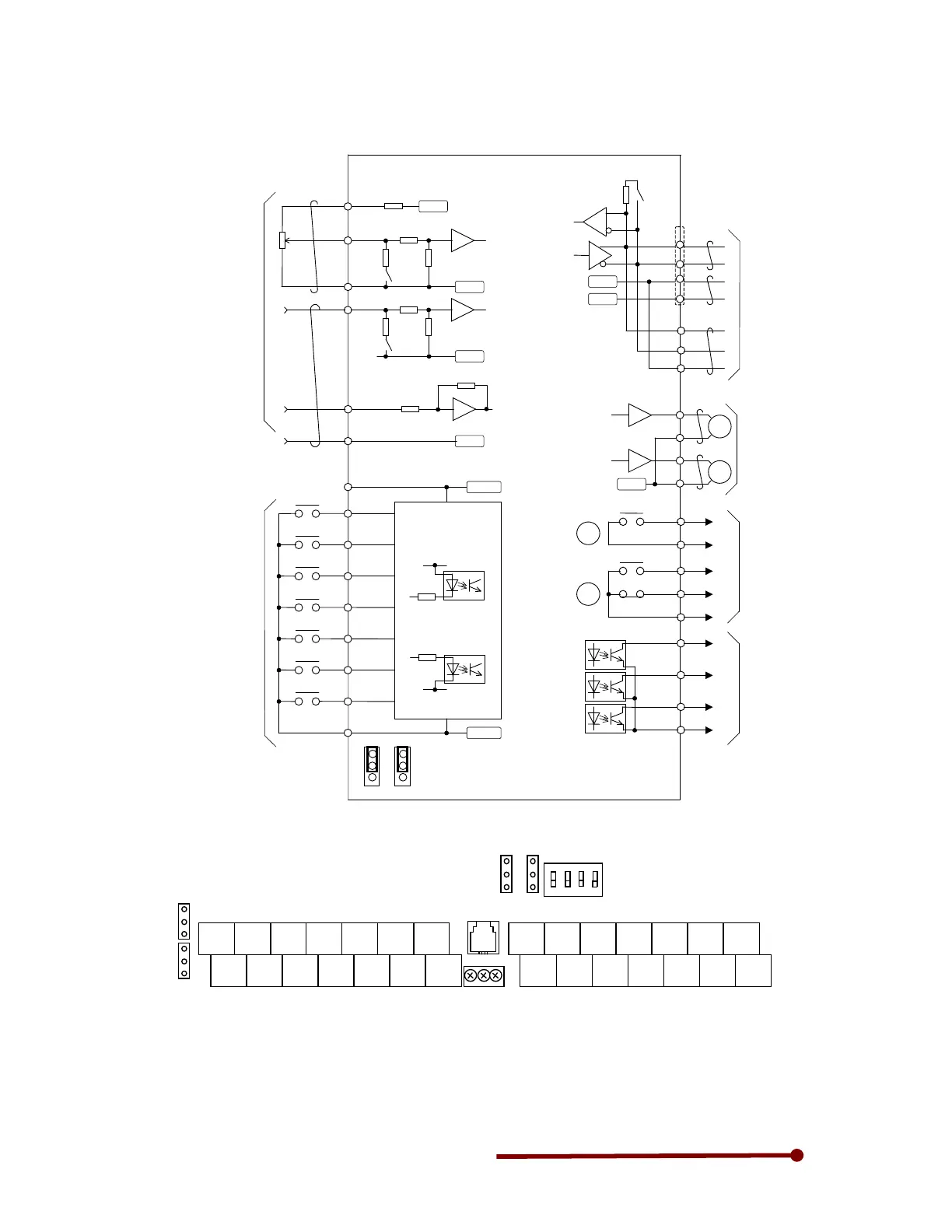
Chapter-5: Control Input/Output
Fig. 5-1-a
F
A
RY
RY
11k
2k
Ω
2W
10kΩ
750
Analog output
• Changeable to 0 to 10V
or 4 to 20mA
0 to 10V max. 1mA
4 to 20mA max. 500Ω
• All terminal functions can
be changed.
Serial communication
(RS-485)
CN2 and TB3 cannot be
used simultaneously.
2
4
1
Terminator
PSO1
PSO2
PSO3
PSOE
DATA+
0VOP
5VOP
DATA+
DATA-
0VOP
3
CN2 : Modular Connector
4.7kΩ
RY24V
4.7k
RY0V
Sink
Source
Sink/source logic changeover
510Ω
11k
10kΩ
510Ω
20kΩ
RA
RC
FA
FB
FC
Sequence output
(Relay output)
• RA-RC
Max. 250VAC 1A
Max 30VDC 1A
• FA-FB-FC
Max. 125VAC 0.4A
Max. 30VDC 1A
• All terminal functions can
be changed.
Sequence output
(Open collector output)
• Max. 30VDC 50mA
• PS03 can be changed to
pulse output
• All terminal functions can
be changed.
Sequence input
• 5mADC
• PSI7 can be changed to
pulse input
•
All terminal functions can be
changed.
Analog input
• AI1, AI2
Changeable to voltage
signal or current signal
Voltage signal max. 10VDC
Current signal max.
20mADC
• A13 max. ±10VDC
•
All terminal functions can be
changed.
Frequency setting
20k
DATA-
Forward run
Emergency stop
Reset signal
Reverse run
Forward jog
Reverse jog
Run
Fault
READY 1
Current
detection
Speed attained
W2
W1
TB3 : Terminal
(Notes)
1. Four COM terminals are internally connected.
2. No connection shall be made between RY0, COM and 0VOP since this section is insulated.
3. This diagram is an example of the sink logic connection.
4. RY24 and RY0 must not be shorted.
5. P10 and COM must not be shorted.
Fig. 5-1-b
PSI4
PSI6
PSO1
PSO3
RY0
RC
RA
CN2
TB1
RY24
PSI2
2
2
2
ON
TB3