Amtech
Chapter-3: Initial Start-
The VT24
0S has various setting items. Some of these include
the power supply and motor before actually starting
The methods for the VT240S basic test operation and
3-1 Selection of Control M
With the VT240S, four control modes a
parameter C30-
0 (control mode selection).
* C30-0 is set with a 2-digit value (
(1) Control modes
Refer to the following table, and select the
Normal-duty
1) V/f control
2) IM sensor-less
vector control
3) IM close loop
vector control
4) PM
loop control
Heavy-duty
1) V/f control
2) IM sensor-less
vector control
3) IM close loop
vector control
4) PM motor
loop control
Normal-duty setting:
Select this when the maximum load rate in respect t
The overload standard will be 120% of the device's
Heavy-duty setting:
Select this when the maximum load rate in res
The overload standard will be 150% of the device's
3-
2 Initialization of motor constants
Input the motor rating parameters.
0S has various setting items. Some of these include settings
that must be made according to
the power supply and motor before actually starting operation.
The methods for the VT240S basic test operation and adjustment are explained in this section.
With the VT240S, four control modes a
nd two overload modes can be selected. These are se
0 (control mode selection).
, f0).
Refer to the following table, and select the
mode, which suits the application.
The IM
is controlled keeping the ratio of voltage and
frequency constant.
The IM is vector-
controlled without a speed sensor.
The speed can be controlled.
PLEASE REFER FULL INSTRUCTION MANUAL
PLEASE REFER FULL INSTRUCTION MANUAL
The IM
is controlled keeping the ratio of voltage and
frequency constant.
The IM is vector-
controlled without a speed sensor.
The speed can be controlled.
PLEASE REFER FULL INSTRUCTION MANUAL
PLEASE REFER FULL INSTRUCTION
Select this when the maximum load rate in respect to the rated load is low.
The overload standard will be 120% of the device's rated current for one minute.
Select this when the maximum load rate in res
pect to the rated load is high.
The overload standard will be 150% of the device's rated current for one minute.
2 Initialization of motor constants
Input the motor rating parameters.
Set the parameters shown in Table 4-2-1.
automatically change the parameters, so it is
recommended to write down the values set
in Table 4-2-2 or Table 4-2-3.
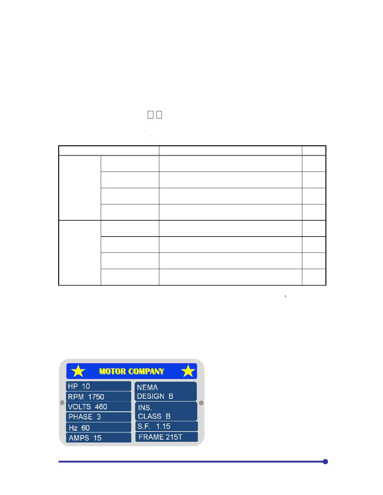
The figure to the left shows the information
provided on a typical AC motor nameplate.
There are several important m
that will be used to program the drive to
provide accurate motor operation and
protection. The motor HP will be
programmed in KW. To change from HP to
KW, multiply by 0.75. The 10HP shown
would be 10 x 0.75 = 7.5KW. For this case
motor, assumin
g the input voltage >460,
B00-0=6, B00-1=2, B00-
that must be made according to
adjustment are explained in this section.
nd two overload modes can be selected. These are set with the
is controlled keeping the ratio of voltage and
11
controlled without a speed sensor.
12
PLEASE REFER FULL INSTRUCTION MANUAL
13
PLEASE REFER FULL INSTRUCTION MANUAL
14
is controlled keeping the ratio of voltage and
21
controlled without a speed sensor.
22
PLEASE REFER FULL INSTRUCTION MANUAL
23
24
pect to the rated load is high.
automatically change the parameters, so it is
recommended to write down the values set
The figure to the left shows the information
provided on a typical AC motor nameplate.
There are several important m
otor values
that will be used to program the drive to
provide accurate motor operation and
protection. The motor HP will be
programmed in KW. To change from HP to
KW, multiply by 0.75. The 10HP shown
would be 10 x 0.75 = 7.5KW. For this case
g the input voltage >460,
-3=460,