Chapter-6:
Control Functions & Parameter Settings
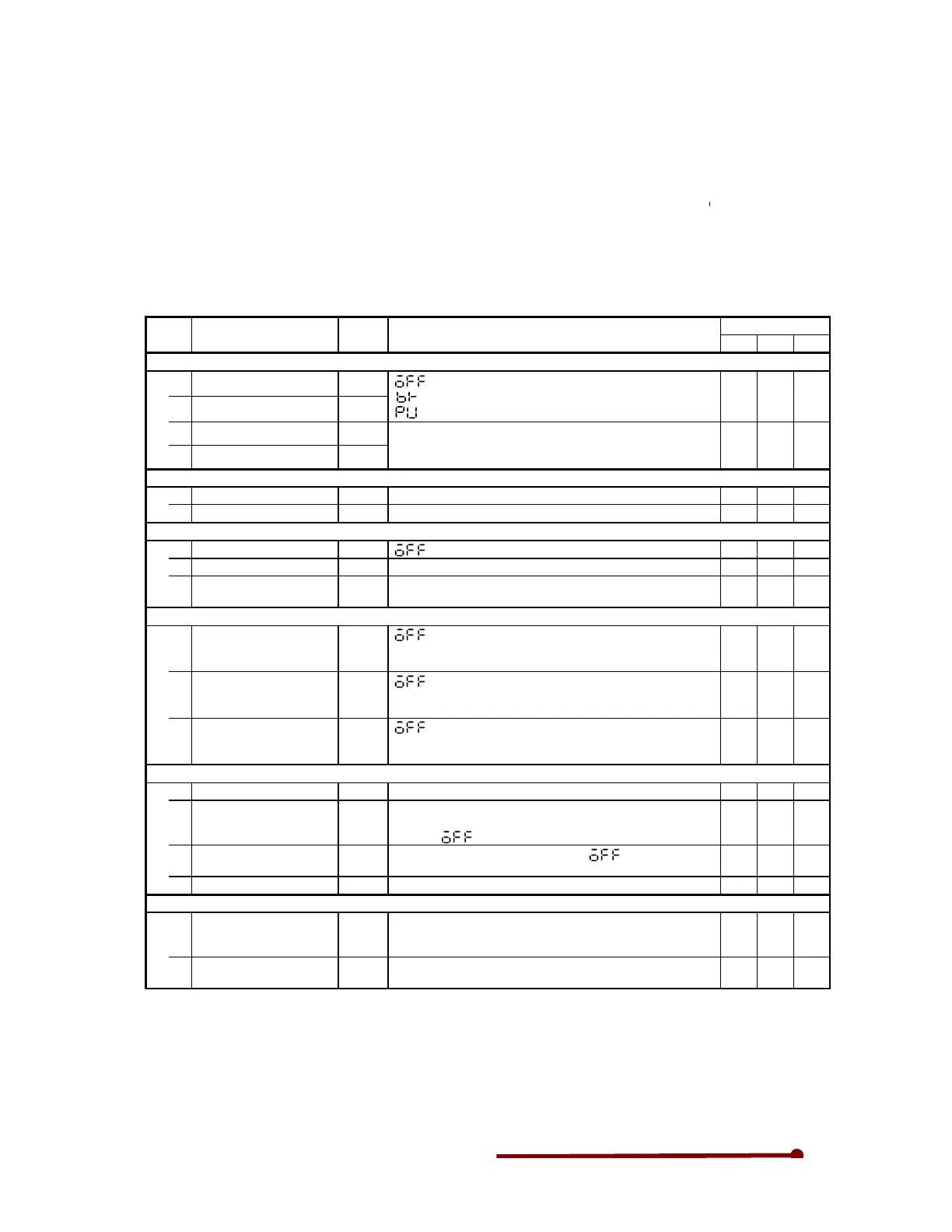
6-1 Monitor parameters
The
monitor mode sequentially displays the frequency, p
the VT240S.
The symbols shown at the right of the list show the
V/f: Indicates parameters that apply for V/f contro
VEC: Indicates parameters that apply for IM speed s
control with sensor (C30-0: f0 = 2,
PM: Indicates parameters that apply for
No. Parameter Unit
D00 – Output frequency monitor
0 Output frequency in Hz Hz
1 Output frequency in % %
2 Motor speed in min
–1
min
–
3 Motor speed in % %
D01 – Frequency setting monitor
0 Set frequency in Hz Hz
1 Set frequency in % %
D02 – Current monitor
0 Output current (Amps) A
1 Output current (%) %
4 Heatsink temperature °C
D02 – Current monitor
7
U phase output current
amps
A
8
V phase output current
amps
A
9
W phase output current
amps
A
D03 – Voltage monitor
0 DC voltage V
1 Output voltage (command)
V
2 Output power kW
3 Carrier frequency kHz
D05 – Minor fault monitor
0 Minor fault monitor
1
Hardware detection fault
status
Control Functions & Parameter Settings
monitor mode sequentially displays the frequency, power supply, etc., parameters recognized by
The symbols shown at the right of the list show the application of each parameter as shown below.
V/f: Indicates parameters that apply for V/f contro
l (constant torque, variable torque) (C30
VEC: Indicates parameters that apply for IM speed sensor
-
less vector control and IM speed vector
PM: Indicates parameters that apply for
control mode with PM motor sensor (C30-0: f0
Monitor parameters list
Remarks
will display when the gate is closed.
displays while the DC brake is in action.
is displayed during pick up.
The forward run direction is displayed with the + polarity, and
the reverse run direction with the –
polarity. (This is displayed
even when stopped.)
The currently selected frequency setting value is displayed.
The max. frequency is displayed as 100%.
will display when the gate is closed.
The motor rated current is displayed as 100%.
Depending on the capacity, OHT.1 functions at 95°C or 120°C
or more.
will display when the gate is closed.
The correct value is not displayed during pick-up or during
automatic tuning.
will display when the gate is closed.
The correct value is not displayed during pick-up or during
automatic tuning.
will display when the gate is closed.
The correct value is not displayed during pick-up or during
automatic tuning.
Displays the voltage of the DC link circuit in the main circuit.
Displays output voltage command. The display may differ from
the actual output voltage. It depends on the power supply
voltage. will display when the gate is closed.
Displays the inverter’s output power.
the gate is closed.
The current carrier frequency is displayed.
The internal minor fault status will display.
The correspondence of each LED segment and signal is
shown in the next page.
The status of the fault signal detected by the hardware is
displayed.
ower supply, etc., parameters recognized by
application of each parameter as shown below.
l (constant torque, variable torque) (C30
-0: f0 = 1).
less vector control and IM speed vector
4).
Application
V/f VEC
PM
{ { {
polarity. (This is displayed
{ {
{
{
{ { {
{ { {
{ { {
{ { {
{ { {
{ { {
{ { {
{ { {
{ { {
{ { {
{ { {
{ { {