Amtech
22
Monitor parameters list
No. Parameter Unit Remarks
Application
V/f VEC
PM
D08 – Input display
3 AI1 input voltage display
V
The voltage on Al1, 2 and 3 terminals will be displayed in a unit
of 0.01V. When the Al terminals are for current setting, “0” will
be displayed.
{ { {
4 AI2 input voltage display
AI3 input voltage display
6 AI1 input current display
mA
The current on the Al1 and A2 terminals will be displayed in a
unit of 0.01mA. When the Al terminals are for voltage setting,
“0” will be displayed.
{ { {
7 AI2 input current display
%
The current or voltage on the Al1, 2 and 3 terminals will be
displayed in % against 10V and 20mA as 100%.
{ { {
D20 – Extended monitor
0 Fault history monitor
The fault history reference mode will display when SET is
pressed.
{ { {
1
Minor failure past record
indication
The minor fault history reference mode will display when
SET is pressed.
{ { {
2
Parameter A, B and C
modification list entry
The mode for referring to and changing parameters that differ
from the default value will display SET is pressed.
{ { {
D21 – Maintenance monitor
0
Cumulative conductivity
time
h.
The cumulative power ON time after product shipment will be
counted and displayed.
{ { {
1 Cumulative run time h.
The cumulative run time after product shipment will be counted
and displayed.
{ { {
2 CPU version Display for maker control.
{ { {
3 ROM version Display for maker control. { { {
D22 – Automatic tuning
0
Automatic tuning
progression display
The progression state of automatic tuning is displayed.
The correspondence of the LED's segments and signals is
shown in the previous section.
{ {
D30 – Hardware monitor
0 Inverter type This indicates the inverter type.
{ { {
1 Option PCB
Displays the mounted option PCB. The correspondence of the
LED segments and signals is shown in the previous page.
{ { {
Note) D30-2 to D30-5 available from the version 9457.0+9458.3
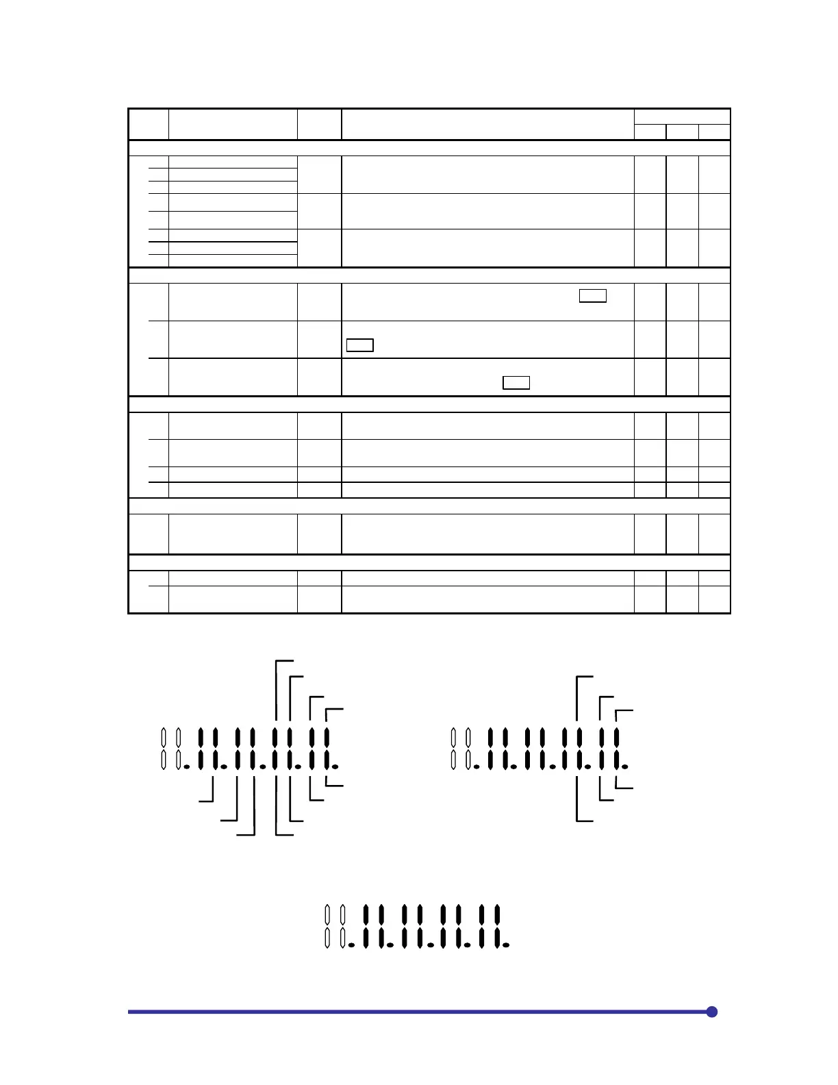
Sequence input terminal status(D08-B)
PSI1
PSI2
PSI3
PSI4
PSI6
PSI8
PSI9
PSI10
PSI11
Speed detection signal input status(D08-C)
A phase
B phase
Z phase
U phase
V phase
W phase
Upper line:
Indication of steps required
for tuning.
Lower line:
Indication of completed steps.
Automatic tuning progress state (D22