Start up Guide for Axpert-VT240S Series AC Drive
33
•
Make sure that water/oil pressure bypass interlocking is tuned as per the programmed
acceleration time of VFD.
Without Built-in PID of VFD
Select Frequency Reference - If it is 0~10V signal, than
C03-D = 16 (On fixed, AFS1 speed setting1)
Connect 0~10V signal wire at VFD’s terminal board as below
0~10V signal (at COM & AI1 terminal)
Select Frequency Reference - If it is 4~20mA signal, than
C03-D = 0 (Off fixed, AFS1 speed setting1)
C03-E = 16 (On fixed, AFS2 speed setting2)
C12-4 = 2: Current input, 4-20mA
Connect signal wire on the VFD control terminal board
4~20mA signal (at COM & AI2 terminal)
•
ON the DIP switch DS1-3 that is available on VFD control board.
Minimum Operating Frequency
Consult to customer for minimum allowable operating frequency (speed) of the compressor which is
declared by manufacturer. If data is not available than program minimum frequency as per below.
B07-1=35Hz (approx 70% of motor base frequency).
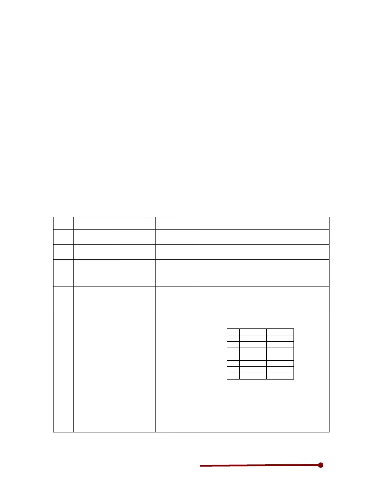
7-5 Hoist Fan Application
No Parameter Unit Def Min Max Description
A01-0 Acceleration
Time-1
Sec 10.0 0.1 6000.0
= 0.5 to 3 Acceleration time
A01-1 Deceleration
Time-1
Sec 20.0 0.1 6000.0
= 0.5 to 3 Acceleration time
A03-0 DC braking
voltage
Invert
er
rating
(%)
0.01 20.00 = 3 to 5% DC braking voltage, Program amount of
current apply for DC braking when DC braking used
during stop.
A03-1 DC braking time Sec 2.0 0.0 20.0 =0.5 to 2 sec, its amount of time that DC braking will
applied when stop command issue.
DC braking is used to hold the motor slippage when
stop command issue.
B00-0 Rated input
voltage setting
(V/f control)
Vac 7 1 7
Select suitable rated input voltage from the below
selections.
Value
200V system
400V system
1 to 200V to 380V
2 to 200V 381 to 400V
3 201 to 220V
401 to 415V
4 201 to 220V
416 to 440V
5 221 to 230V
441 to 460V
6 231 to 240V
461 to 480V
7 221 to 230V
381 to