Installation
6
Axcent
3
and Axcent
3
Pro Integrated Axcess Controllers
RS-232/RS-422/RS-485 connections
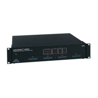
FIG. 4 shows the RS-232/RS-422/RS-485 DB-9 (male) connector pinouts. The table below lists the
connector pins, signal types, and signal functions.
Using the AXlink connector for data and power
Connect the 4-pin AXlink connector to an external AXlink device, as shown in FIG. 5.
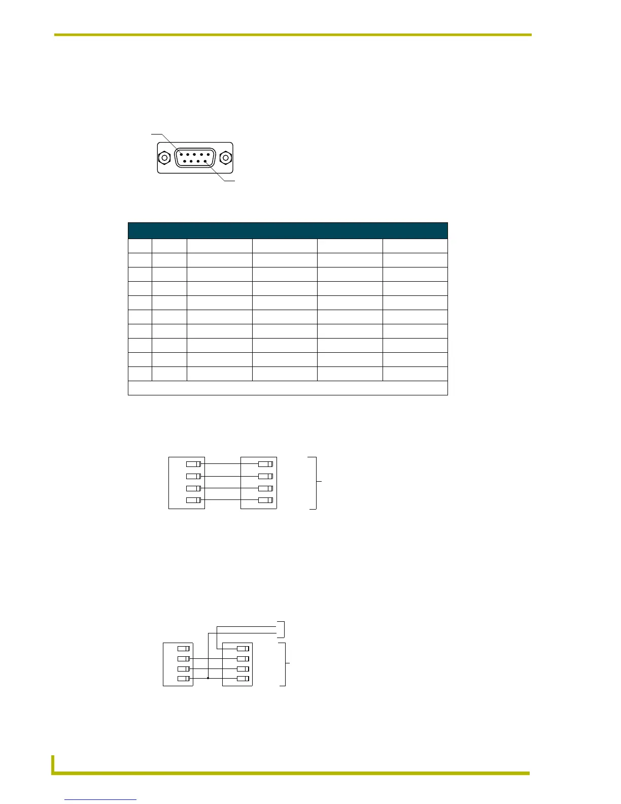
Using the AXlink connector for data with a separate 12 VDC power supply
Connect the 4-pin AXlink connector to an external AXlink device; connect the 2-pin PWR
connector to the separate 12 VDC power supply as shown in FIG. 6. Make sure to connect only the
FIG. 4 RS-232/422/485 DB-9 (male) connector pinouts
DB-9 Pinouts Wiring and Baud Configurations
Pin Signal Function RS-232 RS-422 RS-485
1 RX- Receive data X X (strap to pin 9)
2 RXD Receive data X
3 TXD Transmit data X
4 TX+ Transmit data X X (strap to pin 6)
5 GND Signal ground X X
6 RX+ Receive data X X (strap to pin 4)
7 RTS Request to send X
8 CTS Clear to send X
9 TX- Transmit data X X (strap to pin 1)
The X’s show where to terminate the wires on the DB-9 connector.
FIG. 5 AXlink/PWR data and power wiring diagram
FIG. 6 AXlink/PWR and optional 12 VDC power supply wiring diagram
Pin 9
Pin 1
PWR+
AXP/TX
AXM/RX
GND-
PWR+
AXP
AXM
GND-
AXlink/PWR connector
External AXlink device
PWR+
AXP/TX
AXM/RX
GND-
PWR+
AXP
AXM
GND-
Axcent
3
External AXlink device
PWR+
GND-
Local 12 VDC power supply
for ext. AXlink device
 Loading...