Enova DGX DXLink™ Fiber Boards
126
Hardware Reference Manual – Enova DGX 100 Series Digital Media Switchers
NOTE: The process for removing and replacing transceivers is the same in DXLink Fiber Boards as it is in DXLink Fiber units and the
same for multimode transceivers (black latch) as it is for single mode transceivers (bright blue latch). The photographs in the
procedure below show a DXLink Fiber unit.
In the following procedure, read each step entirely. The steps include helpful tips to avoid damage to DXLink Fiber products. We
also suggest reading the “Tips for Fiber Optic Connections” on page 118.
To remove and replace an SFP+ fiber optic transceiver:
1. If applicable – Label and disconnect fiber optic cables (release the locking tab on the cable connector to disconnect the cable
from the transceiver) or remove dust plugs from the transceiver. If cables from adjoining transceivers or boards obstruct
access, label and disconnect them as necessary.
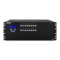
2. Using the tip of the index finger, swing the transceiver latch out and down (orientation of DXLink Fiber Boards varies from
system to system).
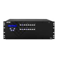
3. Use the handle to release and carefully pull the transceiver completely free from its socket.
4. Restore the removed transceiver’s latch to an upright position and replace the dust plug that originally shipped with the
transceiver. Place the transceiver in an ESD shielded bag and set aside.
TIP: Leave the dust plug in the replacement transceiver for Step 5 to reduce the possibility of damaging the transceiver / socket.
5. With the replacement transceiver’s latch in the up (locked) position, gently insert the transceiver straight into the transceiver
socket until resistance is felt (an audible click will be heard when it is fully seated).
6. Verify proper seating by gently pulling on the transceiver with the latch in the locked position.
7. Remove the dust plug and save for future use.
8. Attach the fiber cable (see page 119).
9. Test the signal path.
FIG. 69 Flip transceiver latch out and down (DXLink Fiber Transmitter shown)
FIG. 70 Pull transceiver free from transceiver socket
 Loading...