Switching, Configuration, and Status
165
Hardware Reference Manual – Enova DGX 100 Series Digital Media Switchers
NOTE: If the enclosure does not include a full set of input/output boards, input and output buttons for connectors that are not
available display with a gray Title bar (i.e., No Card).
Switch Mode buttons – click the A/V (default), Video, or Audio button to select the type of signal to be switched. These buttons
correspond to the available video and audio Virtual Matrices (VMs) in the system. For additional information on the Switch Mode,
see page 166.
NOTE: Switch Mode buttons are only accessible with Audio Switching Boards (ASB or ASB-DAN) in the enclosure.
Inputs section – this section contains buttons for each of the available input signals (per selected Switch Mode) in the system.
Click the input button that needs to be switched. Scroll bars on the right-hand side provide access to any inputs on large systems
which are not currently visible.
Downmix button – the Audio Switch Mode must be selected before the Downmix button displays. The input source used for the
downmix signal is selected on the Configuration page. For complete information on the downmix function, see page 152.
Outputs section – this section contains buttons for each of the available output signals in the system. Click the output button(s)
that needs to receive the signal from the currently selected input button. Note that when the currently selected button is an output,
it also appears in the Configuration page with signal details (for button/signal details, click the Legend button). Scroll bars on the
right-hand side provide access to any outputs on large systems which are not currently visible.
Select All and Deselect All buttons – these buttons appear only after an input is selected. Click as necessary to select or deselect
all output buttons.
Clear button – click to deselect all inputs and outputs (if selected, the Auto Take button state persists) and clear routing status in
the Configuration pane. Note that the Clear button does not disconnect switches. After the Clear button is selected and the input or
one of the outputs already routed is selected, the buttons turn blue to indicate current status. Selecting an output will show status
for the input routed to it, not the other outputs also routed from the same input.
Take button – click to execute the switch for the selected input and output(s). After the switch is made, the current content in the
Switching and Configuration pages persists until further action is taken. Note that the Take button is grayed out until one input and
one or more outputs have been selected for routing; once these conditions are met, the Take button becomes active. After the Take
button is clicked, all of the buttons clear their status.
Selected status bar (non-editable) – this status bar provides quick visual confirmation of input and output selections and their
status (blue = currently routed; yellow = ready to route, waiting further action; blue outline = currently routed, but deselected in
preparation to disconnect).
Switcher Setup button options are available on both the Switching page and the Configuration page.
Save and Load buttons – after a system has been set up per the installation’s requirements, the configuration values for the entire
switcher’s state (i.e., system settings and routing, video and audio settings, channel names, custom EDIDs, etc.) can be saved and
reloaded at any time. The file is saved as a managed content (non-editable) .xdg file with XML and bin data. This file may be
reloaded onto the system it was saved from or loaded onto an identical system or backup system.
Saving – To save a configuration, click the Save button (when the Save button is clicked, there is no direct indication that the file is
being saved). The CPU begins collecting all of the available system data (may take > 2 minutes) and then packages the file for
download. Depending on the browser used in the process, the download may either appear with a Save As dialog box or be saved
directly into your Downloads folder. The default file name is "defaultYYYY-MM-DD.xdg."
Loading – To load a configuration, click the Load button. A Warning appears indicating that the action will override all of the current
configuration values and reboot the switcher. Click Yes and select the saved configuration (.xdg) file from the dialog box. Click Open
to begin the file upload. The file take approximately 30 seconds to load then performs a full system reboot (which takes 3-5
minutes, depending on enclosure size.
While a configuration can be saved at any time, loading a configuration consumes the majority of the available system resources.
For this reason, we recommend disabling code and active switches when loading a configuration. Also, a file should only be loaded
onto a system that matches the configuration of the saved file. If the system receiving the file does not match the original system,
incongruous information (e.g., a DXLink Fiber Input Board is present when the configuration file tries to load HDMI Input Board
information) will be skipped.
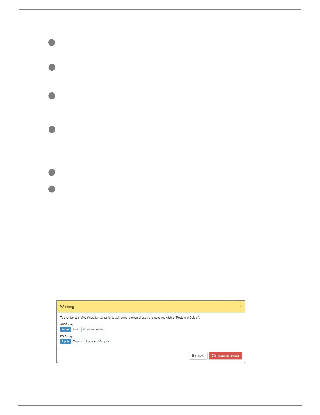
Group Restore to Default button – click to open the Warning dialog box below, which requires you to select an A/V Group and an
I/O Group to restore to their factory default settings.
B
C
D
E
F
G
Save and Load
Buttons
 Loading...