Control Panel Operation
217
Hardware Reference Manual – Enova DGX 100 Series Digital Media Switchers
Input and Output Keys
Input and Output Keys correspond to the input and output connections on the rear of the enclosure. These keys are used to select
the inputs and outputs for routing source signals to destination devices, as well as for status and audio operations. Input Keys are
also used for locking and unlocking the Control Panel.
When an Input or Output Key is pressed, the channel name* displays on the LCD. Hold the key down to display the name longer.
The color of the Input and Output Keys indicate availability or selection:
Blue key – indicates the input or output is available for selection as part of the current operation.
White or flashing white key – indicates an input or output has been selected and that additional action is required to
complete the operation. When verifying Status, the key corresponding to the selected input or output is white; a key(s) for
the input or outputs that are connected to the selected key turn white. When a key is flashing white, it cannot be unselected
and does not display label information on the LCD when pressed. Select another key or press the Cancel Key to unselect.
Non-illuminated key – indicates the input or output is not available for the current operation, e.g., if the enclosure’s
configuration size is not a full 32x32, some keys are always unavailable (never illuminated) because they do not have a
corresponding connector on the rear.
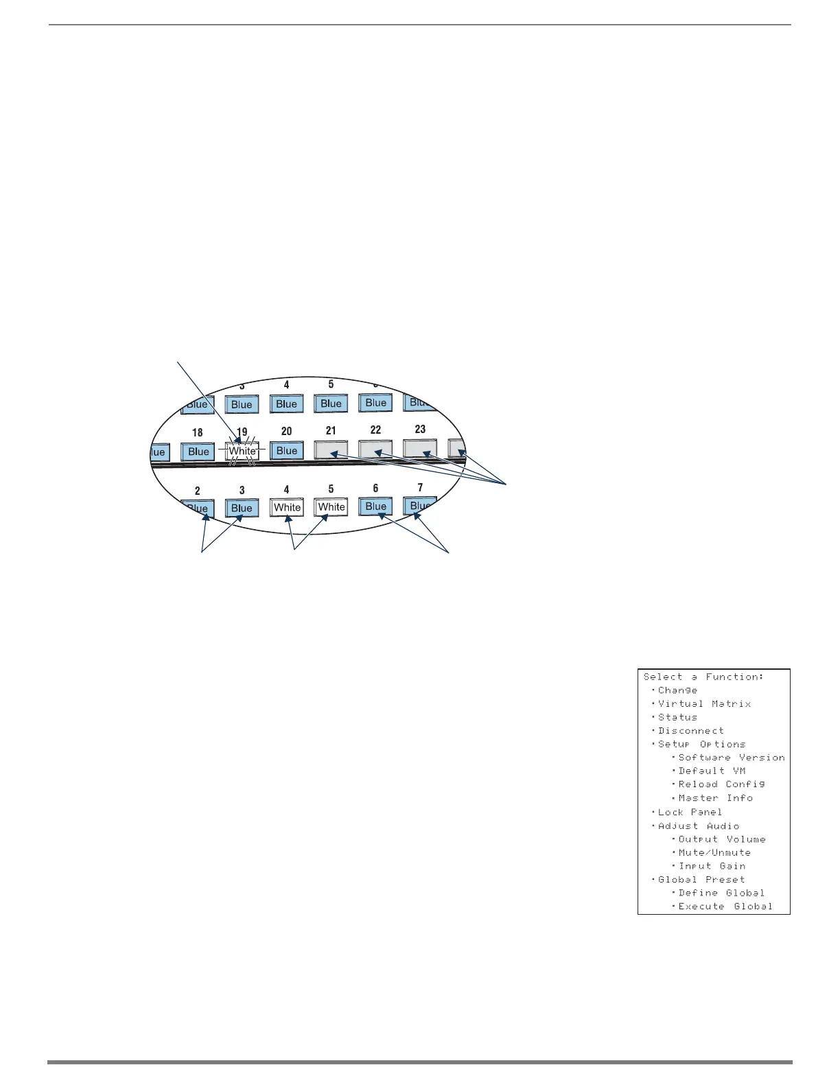
FIG. 114 shows various keys states while in Change Mode. Input Key 19 is flashing white, indicating that input was selected first.
Outputs Keys 4 and 5 are white, indicating that those outputs have also been selected (and can be unselected). The switch from
Input 19 to Outputs 4 and 5 will be executed when the Take Key is pressed. Note that Keys 21 through 24 in the second row of
inputs are not available (i.e., a board has not been installed for these inputs).
* Channel names that have been customized in the System Configuration interface (see page 163) will automatically display on the
LCD when the Input or Output Key is pressed. The channel name default is “Input Name” or “Output Name.” The control panel’s
LCD is limited to 20 characters and will truncate any longer names that are pulled from the System Configuration interface.
Menus and Modes
The Function menu and its submenus access the modes and functions used to control the system.
The modes are Change, Virtual Matrix, Status, Disconnect, Setup Options, Lock Panel, Adjust
Audio*, Global Preset, and Master Info. While in a mode, the same command can be repeated,
without having to return to the Function menu to re-select the mode.
Use the Control Dial and Select Key to navigate the Function menu, and submenus.
The Function menu and the submenus are loop menus, which means that each menu returns to its
first item after you scroll past its last item.
* Adjust Audio Mode is functional only when Audio Switching Boards (ASB or ASB-DAN) are in the
system. When no Audio Switching Boards are present, any commands for Adjust Audio are
ignored.
NOTE: A clear label with white lettering that shows the entire LCD Function menu (as shown on the
right) is included in the Control Panel Label Kit shipped with the system. Dust surface of panel near
the LCD with a dry cloth (if necessary, use a non-abrasive cleaner), peel the backing off of the label,
and firmly press the label on the panel.
The Function menu (see right) and its submenus access the following modes and functions:
Change
Selecting Change places the system in Change Mode. The Control Panel must be in Change Mode
to execute switches. While in Change Mode, select the Input and Output(s) Keys followed by the
Take Key to execute switches (see top of the page).
Virtual Matrix
Selecting the Virtual Matrix Mode accesses the virtual matrices designated for the system in the configuration file (VM 0, VM 1, and
VM 2). The Virtual Matrix Mode can be selected to change the virtual matrix currently used to execute operations (see page 220).
FIG. 114
Example of key states during Change Mode (Control Panel on an Enova DGX 3200)
Key flashing white (input selected)
Blue keys
(outputs available)
White keys
(outputs selected)
Blue keys
(outputs available)
Keys not illuminated
(inputs not available)
Function menu structure
 Loading...