Control Panel Operation
218
Hardware Reference Manual – Enova DGX 100 Series Digital Media Switchers
Status
Selecting Status places the system in Status Mode. Status Mode is used to confirm signal routing or routing to multiple outputs
without risk of accidentally executing a switch (see page 222).
Disconnect
Selecting Disconnect places the system in Disconnect Mode. While in Disconnect Mode, select the Input or Output Key(s) followed
by the Take Key to disconnect switches (see page 221). While in Disconnect Mode, the Control Panel does not indicate the current
routing of selected inputs or outputs.
Setup Options
Selecting Setup Options (see page 228) accesses the Setup Options submenu to check the software version, view information
regarding the integrated Master, change the default virtual matrix, reload the configuration file (when directed to do so by technical
support), and change the password.
Lock Panel
Selecting Lock Panel places the Control Panel in Lock Mode at which time the password is entered to lock the panel. Locking the
panel prohibits access to the system and can prevent accidental switching (see page 224).
Adjust Audio
Selecting Adjust Audio accesses the Adjust Audio submenu. From this menu you can place the panel in Output Volume Mode,
Mute/Unmute Mode, or Input Gain Mode (see page 225).
Global Preset
Selecting Global Preset accesses the Global Preset submenu to execute global presets or define global presets (see page 222).
Enova DGX Control Panel operation consists of the following four basic tasks:
Choosing a mode, submenu, or list: press the Function Key to access the Function menu. Use the Control Dial and Select
Key to choose the desired mode, submenu, list, or list item.
Selecting inputs or outputs: press the corresponding Input or Output Key. Selected keys will change color or flash,
depending on the routing state.
Selecting values for fields: use the Control Dial and Select Key (e.g., virtual matrices, volume, presets).
Executing a command: press the Take Key.
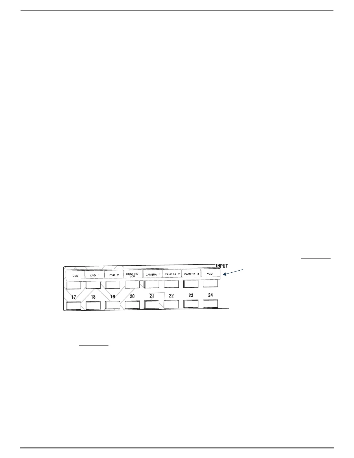
Labeling Input and Output Keys
Each Enova DGX Switcher ships with a kit for custom labeling. To order additional kits, contact your AMX representative. The
Control Panel Label Kit (KA1056-01) includes:
Perforated card stock sheets – Print, separate labels, and slide into holders.
Label holders – Attach to the front panel above each row of Input and Output Keys.
LCD Function menu label – Shows entire LCD menu structure (see Note on previous page).
The label template (.xlt template formatted in Microsoft Excel) for labeling the input and output keys is available at www.amx.com.
TIP: When the labels are ready to print, we recommend printing a sample on plain paper first.
To create and install labels for Input and Output Keys:
1. At www.amx.com, search for Control Panel Label Form Template.
2. Under AutoPatch Tools in the right-hand column, click on Control Panel Label Form Template.
3. Type the labels in the preformatted cells on the template according to the instructions in the template (if desired, use standard
Excel editing tools to alter font size, spacing, color, etc.). Do not modify the cell size.
4. Save the file for future use (recommended).
5. Print the labels on the perforated sheets provided, using any standard laser printer.
6. Trim off the excess label insert material where indicated.
7. Separate the label strips at their perforations (bend back and forth first).
8. Slide the first label strip into a plastic label holder (position with open edge of holder up).
9. Peel the adhesive backing off the label holder and press the holder firmly onto the Control Panel above the appropriate Input
or Output Keys. The silk screened labels on the front panel will aid in label holder alignment.
10. Repeat Steps 8 and 9 for the remaining labels.
FIG. 115
Customize labels to designate sources and destinations (Control Panel on an Enova DGX 3200)
Slide label into holder before
attaching to Control Panel
 Loading...