Appendix B – Replacing Battery on CPU
241
Hardware Reference Manual – Enova DGX 100 Series Digital Media Switchers
6. Use the tab indicated in FIG. 123 to pull the CPU board approximately four inches straight out of the enclosure.
7. Locate the CPU battery on top of the CPU.
8. Pull the dead battery out from under the bracket that holds it in place.
TIP: Place thumbnail into access slot under front side of battery and simultaneously push down on the far lip of the battery while
pulling the battery clear of the bracket.
9. Dispose of battery as mandated by your area or country guidelines.
10. Slide the replacement battery, positive side up (+), into place under the battery bracket.
11. Slowly push the CPU board back into the slot firmly enough to make a good electrical connection (avoid pushing on the
connectors). When the board is fully inserted, the faceplate that covers the CPU should sit flush with the back metal.
12. Reattach the faceplate with the screws that were removed in Step 3 (Enova DGX 800/1600/3200) or Step 4 (Enova DGX
6400).
13. Plug in all AC power cords.
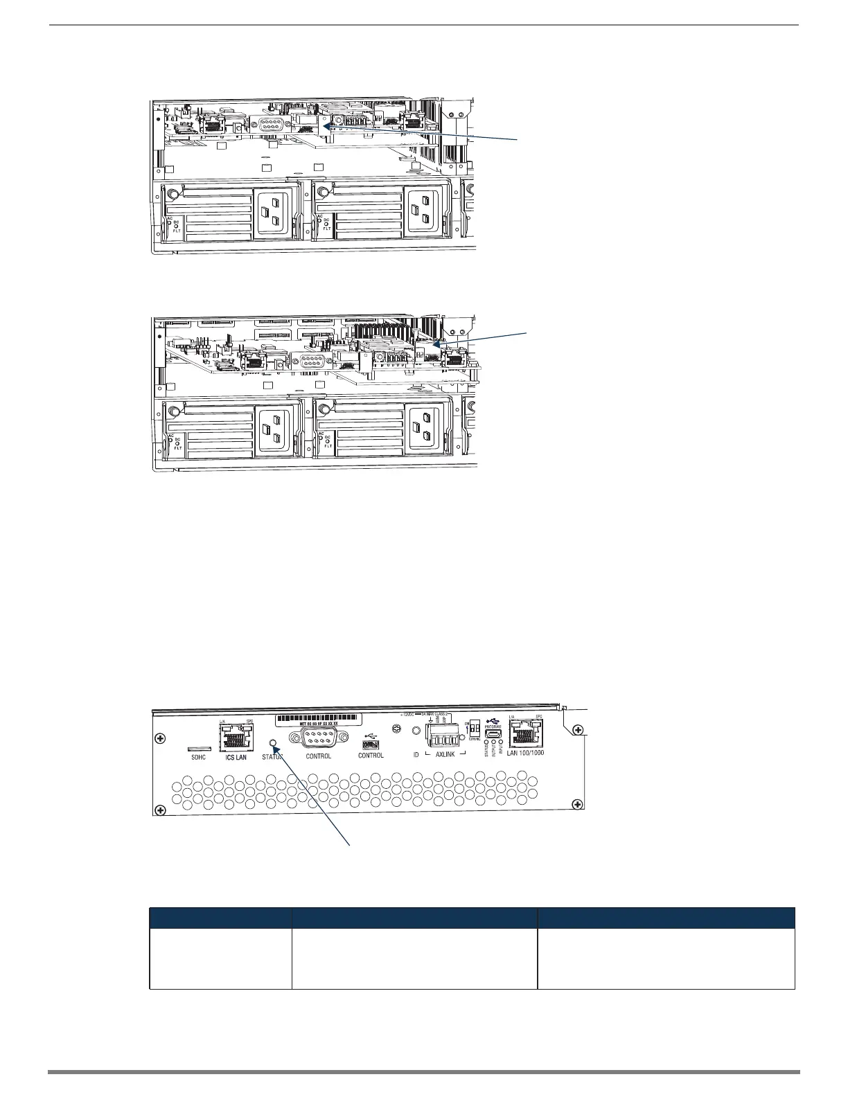
14. Check the Status LED on the CPU for indications of normal display (see table below FIG. 125).
15. Re-attach the cables that were removed in Step 2 and replug the AxLink connector.
16. Execute a test switch to be sure the system is working correctly (see page 219).
FIG. 123
Use tab indicated to pull CPU board about four inches straight out (Enova DGX 6400 shown)
FIG. 124 Locate CPU battery on top of the CPU in battery bracket
FIG. 125 Check System Status LED indicator on CPU
CPU LED Indicator Normal Display Cautionary Display
System Status • Solid amber during boot load (10 sec)
• Solid green during app load (1-4 minutes,
depending on system configuration)
• Flashing green when ready
Blinking red/green: MCPU is in a fault state. Power
cycle may recover; otherwise, contact technical
support.
Tab for pulling CPU board
TIP: The CPU battery is fully exposed when
the CPU board is extended four inches.
CPU battery in bracket
System Status LED
 Loading...