UG-1134 EVAL-ADAU1467Z
Rev. A (Draft) | Page 16 of 55
Figure 38. Serial Ports Connections to the AD1937 Codec
Add screen shots of SPORT tabs (in, out, SDATAIOx)
AD1937 Boot Mode
Expand on this.
The AD1937 is capable of running in standalone mode or being
booted and configured through its I
2
C control port. Switch S2
selects the boot mode of the AD1937 codec as shown in Figure 39,
and this switch is set to STANDALONE by default. When
running in standalone mode, the serial ports of the AD1937 are
configured as clock slaves. Therefore, the corresponding serial
ports on the ADAU1467 must be set as clock masters. By default,
all serial ports on the ADAU1467 are set as clock masters when a
new project is created in SigmaStudio.
Standalone mode eliminates the need for the user to configure
the registers of the AD1937 via its I
2
C port. This mode fixes the
sample rate of the AD1937 at 44.1 kHz or 48 kHz. The analog
audio inputs and outputs on the EVAL-ADAU1467Z can be
distorted or silent if a sample rate other than 44.1 kHz or 48 kHz is
used for the ADAU1467 serial ports.
The alternate I
2
C master port pins of ADAU1467 are connected
to the I
2
C control port of the AD1937 when Switch S2 is set to I
2
C
boot mode; this requires reconfiguration of the master control
port from SPI to I
2
C and enabling the alternate I
2
C port on the
MP24 pin and MP25 pin. This configuration is beyond the scope of
this user guide; however, it enables the ADAU1467 to boot and
configure all of the control registers of the AD1937. When
configured manually, the codec is flexible and can run at
any sample rate up to 192 kHz.
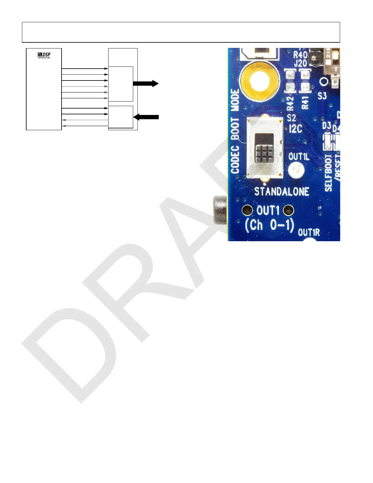
Figure 39. AD1937 CODEC Boot Mode Selection Switch S2
Booting the CODEC from the DSP Using I
2
C
How to config to 96 kHz.
Create an XML file manually or using the following steps
1. Add AD1937 block to hardware config tab to access GUI for
registers.
2. Configure the CODEC
3. Copy commands from output window to sequence window
• Serial port & SDATAIOx mapping
o Setting up mapping for ADCs/DACs
o CODEC boot mode switch
o Creating a XML file
o Adding boot block to SigmaStudio schematic
8-CHANNEL
DAC
(4 × I
2
S)
4-CHANNEL
ADC
(2 × I
2
S)
AD1937
CODEC
ANALOG OUT
ANALOG IN
DAC FRAME SYNC
DAC BIT CLOCK
OUTPUT CHANNELS 0-1
OUTPUT CHANNELS 4-5
ADC FRAME SYNC
ADC BIT CLOCK
INPUT CHANNELS 32-33
INPUT CHANNELS 36-37
OUTPUT CHANNELS 8-9
OUTPUT CHANNELS 12-13
15786-081
LRCLK_OUT0
BCLK_OUT0
SDATA_OUT0
LRCLK_IN2
BCLK_IN2
SDATA_IN2
SDATAIO4
SDATAIO6
SDATAIO7
ADAU1467
SDATAIO5

 Loading...

