User’s Manual for
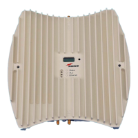
MRx18 Rel. 2 Single-Band
Page 48 M0139ADD.doc
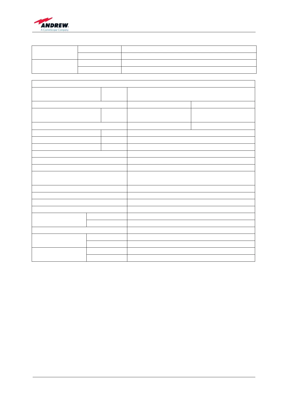
Connector SMA Female
Antenna port
Return loss 10 dB
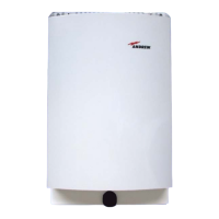
Antenna gain 2.0 dBi Indoor antenna
(optional)
Radiation Omni
MR1718
Frequency range
UL
DL
1710 MHz to 1755 MHz
2110 MHz to 2155 MHz
UMTS CDMA
RF output power
2)
UL / DL
+18 dBm @ 1 carrier
+15 dBm @ 2 carriers
+22 dBm @ 1 carrier
+19 dBm @ 2 carriers
Spurious emission
According to 3GPP <-13 dBm
OICP3 UL/ DL +41 dBm
P-1dBc UL/ DL +28 dBm
Noise figure UL/ DL 6.0 dB @ maximum gain
Gain 70 dB
Gain adjustment range 30 dB in steps of 1
Input and output impedance 50 Ohms
Bandwidth options
3)
variable 1 MHz to 25 MHz
in steps of 10 kHz
Flatness ±3 dB
Delay 5 µs
Delay ripple ±200 ns
EVM 8%
Mains Power 100 Vac to 240 Vac
Power supply
Local Power 6 Vdc
Power consumption 20 watts
Connector SMA Female
Antenna port
Return loss 10 dB
Antenna gain 2.0 dBi Indoor antenna
(optional)
Radiation Omni
All figures are typical values.
2)
) Note: The manufacturer's rated output power of this equipment is for single carrier
operation. For situations when multiple carrier signals are present, the rating would
have to be reduced by 3.5 dB, especially where the output signal is re-radiated and
can cause interference to adjacent band users. This power reduction is to be made
by means of input power or gain reduction and not by an attenuator at the output of
the device.
3)
Recommended bandwidth for UMTS carriers:
1 carrier: 4.6 MHz
2 carriers: 9.6 MHz
3 carriers: 14.6 MHz
All data is subject to change without notice.
 Loading...