Page 5
FIGURES AND TABLES
figure 3-1 Block diagram................................................................................................15
figure 3-2 Connectors of MRx18....................................................................................16
figure 4-1 MRx18, position of screws for wall mounting.................................................17
figure 4-2 Power connection of DC connector with MRx18............................................18
figure 5-1 Login, correct.................................................................................................21
figure 5-2 Login, incorrect..............................................................................................22
figure 5-3 Status – General & Alarms, exemplary..........................................................24
figure 5-4 Status – General & Alarms, high-contrast page.............................................24
figure 5-5 Settings – Radio Frequency, exemplary........................................................27
figure 5-6 Settings - Radio Frequency, high-contrast page ...........................................27
figure 5-7 Settings – Alarms ..........................................................................................30
figure 5-8 Settings – Alarms, high-contrast page...........................................................30
figure 5-9 Settings – Modem Control.............................................................................31
figure 5-10 Settings – Modem Control, high-contrast page ...........................................31
figure 5-11 Settings – LAN Connectivity........................................................................33
figure 5-12 Settings– LAN Connectivity, high-contrast page .........................................33
figure 5-13 Settings - User Account...............................................................................36
figure 5-14 Settings – User Account, high-contrast layout.............................................36
figure 5-15 Maintenance................................................................................................37
figure 5-16 Maintenance, high-contrast page ................................................................37
figure 5-17 Logout .........................................................................................................39
figure 5-18 Upload new software version ......................................................................40
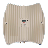
figure 6-1 Coverage antenna for MRx18, optional equipment .......................................41
figure 7-1 Display and alarm LEDs, exemplary..............................................................43
figure 7-2 Display with reset button and alarm LEDs , exemplary .................................44
figure 7-3 Display – RSSI ..............................................................................................45
figure 7-4 Display – Gain UL and DL.............................................................................45
figure 7-5 Display – P
out
UL and DL...............................................................................45
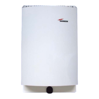
figure 8-1 Cabinet drawing MRX18................................................................................51
table 1-1 List of international contact addresses............................................................11
table 5-1 Status bar, description....................................................................................23
table 5-2 Status page ....................................................................................................25
table 5-3 Settings – User Account page ........................................................................36
table 5-4 Maintenance page, description.......................................................................39
table 7-1 Alarm LEDs ....................................................................................................44