SWR (Return Loss) and Cable Loss Measurement
The following frequency domain measurement is an example of a Standing Wave Ratio (or
Return Loss) and Cable Loss measurement made over a selectable frequency range. This
measurement example determines the quality and loss of the cable or device under test.
Required Equipment
·
Site Master Model S113B, S114B, S331B, or S332B
·
Precision Open/Short, Anritsu 22N50 or
Precision Open/Short/Load, Anritsu OSLN50LF
·
Precision Load, Anritsu SM/PL
·
Test Port Extension Cable, Anritsu 15NNF50-1.5A
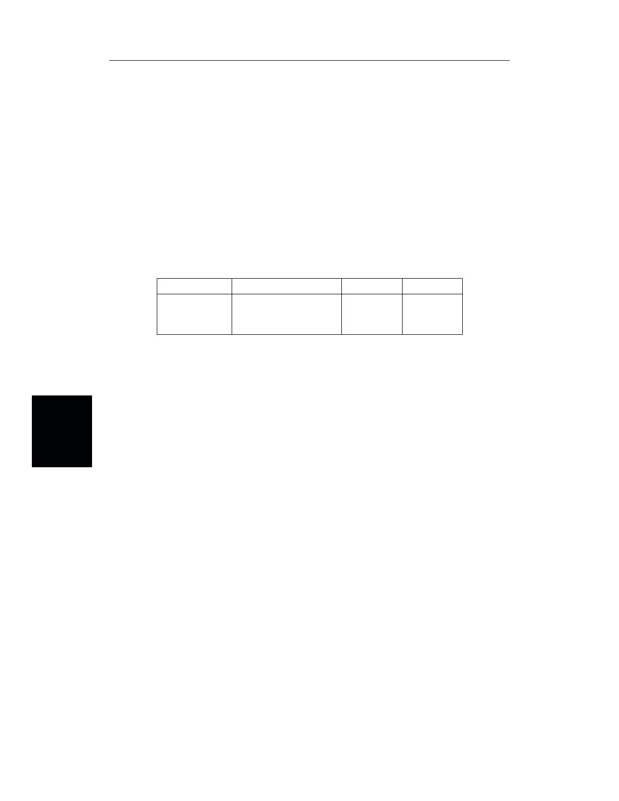
Device-Under-Test Specification
Procedure
Step 1. Press the ON/OFF key on the Site Master.
Selecting the Measurement Mode
Step 2. Press the MODE key.
Step 3. Use the Up/Down arrow key to scroll to
FREQ-SWR or FREQ-RETURN LOSS.
Step 4. Press the ENTER key to select Frequency SWR or Return Loss measurement
mode.
Selecting the Frequency Range
Step 5. Press the FREQ/DIST key.
Step 6. Press the
F1 soft key.
Step 7. Enter 2, 5 using the key pad or the Up/Down arrow key.
Step 8. Press
ENTER to set F1 to 25 MHz.
Step 9. Press the
F2 soft key.
Step 10. Enter 1, 2, 0, 0 using the keypad or the Up/Down arrow key.
Step 11. Press
ENTER to set F2 to 1200 MHz.
Step 12. Check that the FREQ (MHz) scale in the display area indicates the new fre
-
quency start and stop values (F1 = 25 MHz, F2 = 1200 MHz).
4-6
Chapter 4 Measurements
Type Typical Loss @1.5m V
g
Return Loss
15NNF50-1.5A
0.3 dB @300 MHz
0.4 dB @600 MHz
0.5 dB @900 MHz
0.6 dB @1200 MHz
0.86 ³ 21 dB