IQ-636X-2/E Installation Manual — P/N 52853:K3 9/28/15 35
Output Relay Connections Installation
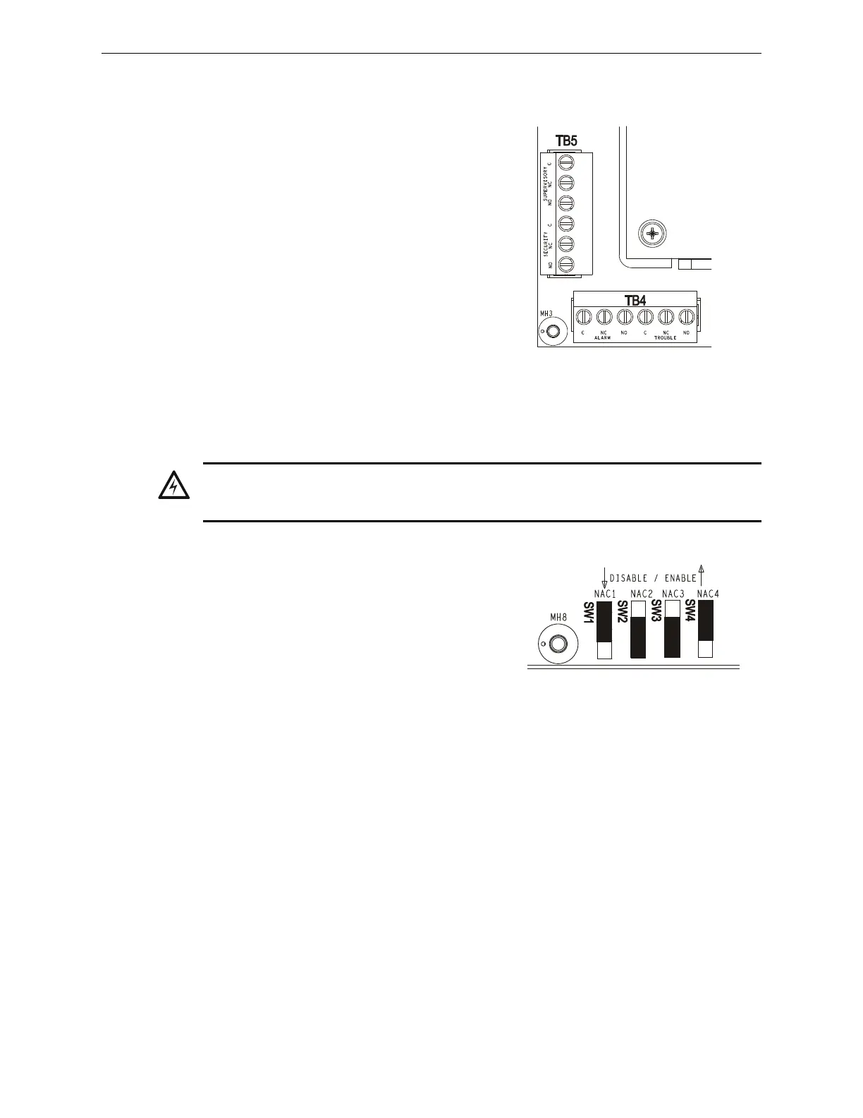
3.9 Output Relay Connections
The panel provides a set of Form-C relays. These
are rated for 2.0 A at 30 VDC (resistive):
• Alarm - TB4
• Trouble - TB4
• Supervisory - TB5
• Security - TB5
These are power-limited only if connected to a
power-limited source.
Using VeriFire Tools, the Supervisory and
Security contacts can also be configured as Alarm
contacts. Follow instructions in the VeriFire Tools
online help.
3.10 Backup-Alarm Switches
Backup alarm switches are provided that enable NACs
and the alarm relay to activate during a backup alarm
condition. If the main board’s microcontroller fails and
an alarm is reported by any detector or a monitor
module that has backup reporting enabled, the NAC
will turn on if the corresponding switch was enabled.
The alarm will activate during microcontroller failure
regardless of the settings of switches SW1–SW4.
• SW1 - NAC#1
• SW2 - NAC#2
• SW3 - NAC#3
• SW4 - NAC#4
So, for example, if SW1 and SW4 were enabled at the time of an alarm during microcontroller
failure, NAC#1 and NAC#4 would activate. Follow sequence of steps in Section 3.2 “Installation
Checklist”, Table 3.1; this is Step 7.
CPU2-640-relays.wmf
Figure 3.19 Form-C Relay
Connections
WARNING:
Do not enable the BACKUP option switch for any of the four Notification Appliance Circuits (NACs) if
they are used for releasing functions!
Figure 3.20 Backup Alarm
Switches
CPU2-640-bckalm.wmf

 Loading...