38 IQ-636X-2/E Installation Manual — P/N 52853:K3 9/28/15
Installation Installing Remote Printers and/or CRT
This section contains information on connecting a printer to the control panel and for setting the
printer options.
Connecting a Remote PRN Series Printer
Remote printers require a 120 VAC, 50/60 Hz primary power source. If required for the fire alarm
system configuration (for example, a Proprietary Fire Alarm System), a remote printer requires a
secondary power source (battery backup). Because a secondary power source is not provided, use a
separate Uninterruptable Power Supply (UPS) that is UL-listed for Fire Protective Signaling. You
may use your building emergency power supply, so long as it meets the power continuity
requirements of NFPA 72. Refer to NFPA 72 for further details.
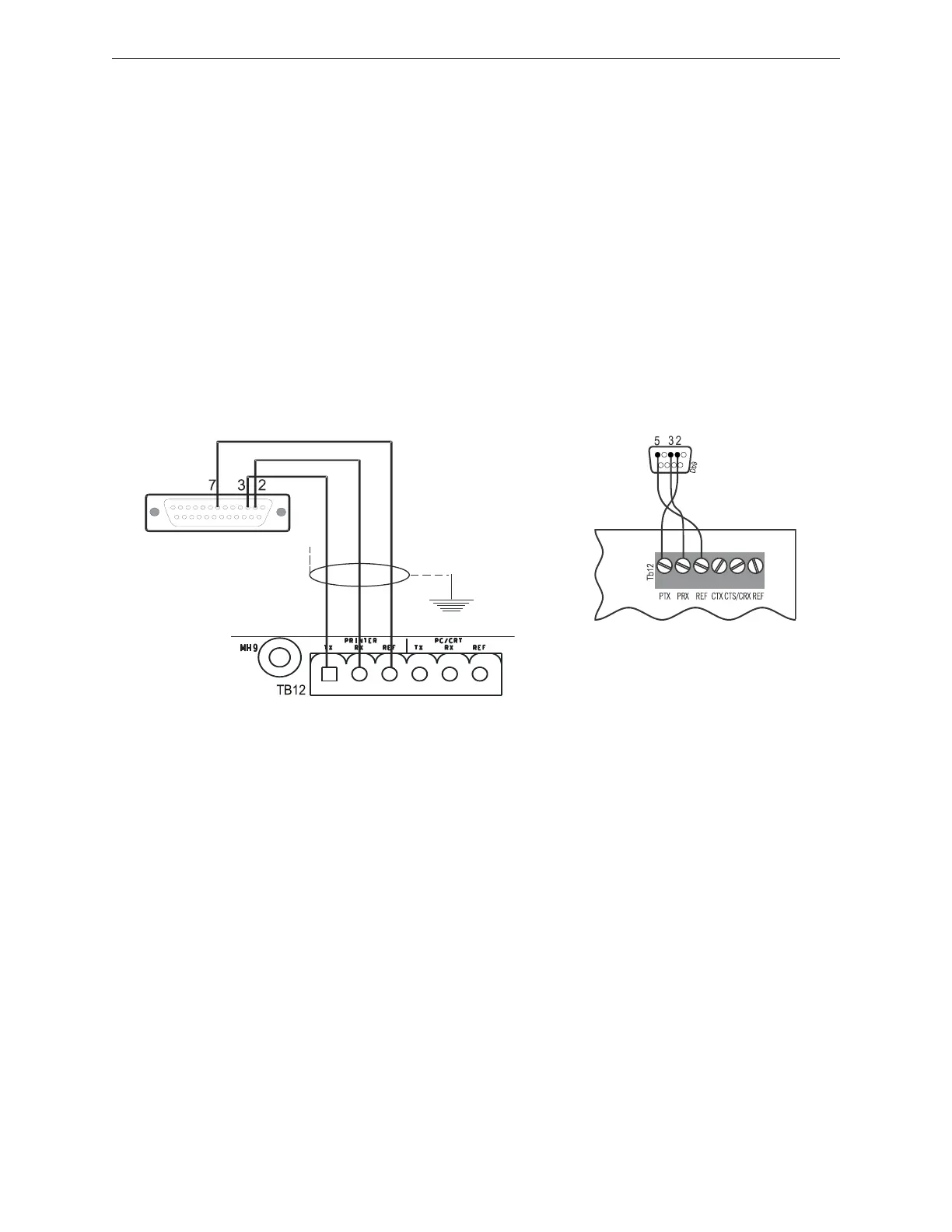
Connect the remote printer to the Control Panel as follows:
1. Connect the three (3) open leads of the custom cable to the TB12 terminal block on the control
panel as shown in Figure 3.23.
2. Plug the DB-25 or DB-9 connector end of the custom cable into the EIA-232 port of the remote
printer. Tighten securely.
Setting Printer Options
Refer to the documentation supplied with the PRN series printer for instructions on using the
printer menu controls. Set the printer options (under the menu area) according to the settings listed
in Table 3.6.
Figure 3.23 Remote Printer Connections
DB-25 connector on PRN series printer (female socket shown)
Terminate one end
of shield at
backbox
Control Panel
CPU2-640-PRN.WMF
DB-9 Connector on PRN series Printer
NOTE: Outputs are power-limited but are not supervised
DB9printer.wmf

 Loading...