EasyManua.ls Logo

AOC LC32D1322 User Manual

AOC LC32D1322
172 pages
To Next Page IconTo Next Page
Page #1 background image
32& 42LCD TV AOC LC32D1322-LC42D1322-LE32D1322
Copyright © 2012 by TPV Corporation. All rights reserved. Specifications are subject to change without notice.
No part of this publication may be reproduced in any form or means, without the prior written permission of TPV Corporation. Otherwise we will
reserve the right to investigate the legal responsibility.
Service
Service
Service
Horizontal Frequency
31~64 KHz(LC32D1322/LE32D1322)
31~80KHz(LC42D1322)
TABLE OF CONTENTS
Description Page Description Page
SAFETY NOTICE
ANY PERSON ATTEMPTING TO SERVICE THIS CHASSIS MUST FAMILIARIZE HIMSELF WITH THE
CHASSISAND BE AWARE OF THE NECESSARY SAFETY PRECAUTIONS TO BE USED WHEN SERVICING
ELECTRONIC EQUIPMENT CONTAINING HIGH VOLTAGES.
CAUTION: USE A SEPARATE ISOLATION TRANSFOMER FOR THIS UNIT WHEN SERVICING
6.2 Power Board……...…………..….…….……….......46
6.3 Key Board……………………….……..……….......55
6.4 IR Board………………………….……..……….......56
7. Adjustment..............................................................57
7.1 ADC Adjustment……………………..……...………57
7.2 FW Upgrade.………………………………...………58
8. Block Diagram.…….................................................59
9. Schematic Diagram…..…………....………………...60
9.1 Main Board…………………………………...….......60
9.2 Power Board…………..….….……...………….......77
9.3 Key Board……………….……….…………….........82
9.4 IR Board……………….……….…………….........84
10. Exploded View………………………………….…...86
11. BOM List……………….………………….………….92
Table of Contents.......……....................................…........1
Important Safety Notice.......................................……......2
Revision List…………………………………………………3
1. General Specification..............................……...…........4
2. Operating Instructions………………...…….……….......6
2.1 The Use of Remote Control…….…..……….…….......6
2.2 To Use the Menus….....………………….…..…….......7
2.3 How to Connect……..……………….…….……….....14
2.4 Front Panel Control Knobs…….………….……….....16
3. Input/Output Specification…………....................…....20
4. Mechanical Instructions…………………….................23
5. Repair Flow Chart ……………………….…….…….....35
6. PCB Layout ………………..…………………....….......42
6.1 Main Board…………..……………...…….…….......42
Question and Answer IconNeed help?

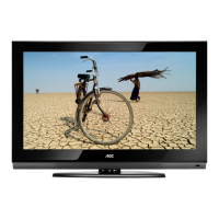
Do you have a question about the AOC LC32D1322 and is the answer not in the manual?

AOC LC32D1322 Specifications

General IconGeneral
BrandAOC
ModelLC32D1322
CategoryLCD TV
LanguageEnglish

Summary

Service Manual Overview

Safety Precautions for Servicing

Important Safety Notices

Warning on Substitute Parts

Caution against using non-specified replacement parts that may cause hazards.

Laser Safety Precautions

Specific safety guidelines for products containing laser components.

Use of Original Replacement Parts

Emphasizes using only original manufacturer's replacement parts for continued reliability.

LCD Module Handling Precautions

Specific instructions for safely handling the LCD module with backlight unit.

Revision History

General Specifications (LC32D1322/LC42D1322)

General Specifications (LE32D1322)

Operating Instructions

Remote Control Operation

Explains the function of each button on the remote control for operating the TV.

Using TV Menus

Menu Navigation Instructions

Provides step-by-step guidance on navigating through TV menus using the remote control.

Initial Setup Guide

Guide for initial TV setup, including language and channel tuning.

Image Menu Settings

Advanced Image Settings

Details advanced picture adjustment options for optimizing video quality.

Sound Menu Settings

Sound Mode Selection

Allows selection of sound modes such as Stereo, SAP, or Mono.

Active Backlight Settings

Adjusts backlight for optimal brightness and color saturation.

TV Menu Settings

Tuner Mode Selection

Selects the TV tuner mode, such as Cable or Antenna.

Automatic Channel Scan

Performs automatic channel search and storage.

Audio Mode Selection

Selects audio modes like Stereo, SAP, or Mono.

Configuration Menu Settings

Language Settings

Allows selection of the menu language.

Appropriate Display Format

Configures the display format for proper visualization.

Factory Reset Function

Resets all configurations to factory defaults.

Parental Controls Menu

Channel Blocking

Blocks channels based on parental control settings.

Digital Classification

Defines channel classifications for digital TV content.

Change Password

Changes the parental control password.

Media Menu for USB Playback

Connecting Equipment

Antenna Connections

Instructions for connecting analog or digital antennas to the TV.

DVD Player Connections

Details on connecting DVD players via HDMI and AV (component) interfaces.

HDMI Connection Guide

Instructions for connecting devices using HDMI for high-quality video output.

Camera to AV Connection

Front Panel Control Knobs

Control Knob Usage Instructions

Details the operational use of each control knob on the TV's front panel.

Peripheral Connection Guide

Side Panel Connections

Identifies and explains connections available on the TV's side panel.

Rear Panel Connections

Identifies and explains connections available on the TV's rear panel.

Component Input

Connects devices using component video (YPbPr) and audio inputs.

PC Input

Connects computers using VGA for video and audio signals.

Front Panel Controls (LE32D1322)

Lateral Control Panel Usage

Detailed instructions on how to use the controls located on the side panel of the TV.

Input/Output Specifications

RGB Signal Input Details

Describes the pin assignments for a standard 15-pin color display signal cable.

HDMI Connector Pin Assignments

Lists the pin assignments for HDMI digital connectors.

Compatible Input Modes

HDMI Input Signal Timing

Mechanical Disassembly (LC32D1322)

Removing the Base (LC32D1322)

Step-by-step instructions for removing the TV's base unit.

Removing the Rear Cover (LC32D1322)

Instructions for removing the rear cover of the LC32D1322 TV chassis.

Removing Boards and Components (LC32D1322)

Removing Brackets (LC32D1322)

Instructions for removing specific brackets from the assembly.

Separating Panel and Removing IR Board (LC32D1322)

The Bezel Component (LC32D1322)

Mechanical Disassembly (LC42D1322)

Removing the Base (LC42D1322)

Step-by-step instructions for removing the TV's base unit.

Removing the Rear Cover (LC42D1322)

Instructions for removing the rear cover of the LC42D1322 TV chassis.

Removing Boards and Components (LC42D1322)

Removing Brackets (LC42D1322)

Instructions for removing specific brackets from the assembly.

The Panel Component (LC42D1322)

The Bezel Component (LC42D1322)

Illustrates the bezel component of the LC42D1322 TV.

Mechanical Disassembly (LE32D1322)

Removing the Base (LE32D1322)

Step-by-step instructions for removing the TV's base unit.

Removing the Rear Cover (LE32D1322)

Instructions for removing the rear cover of the LE32D1322 TV chassis.

Removing Boards and Speakers (LE32D1322)

Removing IR Board and Cover (LE32D1322)

The Panel Component (LE32D1322)

The Bezel Component (LE32D1322)

Illustrates the bezel component of the LE32D1322 TV.

Repair Flow Chart: No Power

Troubleshooting: No Power

Diagnostic steps for when the TV has no power and the LED is off.

Troubleshooting: TV Not Turning On

Troubleshooting: Abnormal Image

Troubleshooting: No Image

Troubleshooting: Sound Issues

Troubleshooting: Remote Control Malfunction

Troubleshooting: Unstable OSD

PCB Layout: Main Board

Main Board PCB Layout

Detailed layout of the main board PCB, showing component placement.

PCB Layout: Power Board (LC32D1322)

PCB Layout: Power Board (LC42D1322)

PCB Layout: Power Board (LE32D1322)

PCB Layout: Key Board

Key Board Layout (LE32D1322)

Specific layout for the key board used in the LE32D1322 model.

PCB Layout: IR Board

IR Board Layout (LE32D1322)

Specific layout for the IR board used in the LE32D1322 model.

Adjustment Procedures

Firmware (F/W) Upgrade Process

F/W Upgrade Preparation

Steps to prepare the software file and USB disk for firmware upgrade.

Performing F/W Upgrade

Procedure for connecting the USB drive and initiating the firmware upgrade.

System Block Diagram

Schematic Diagram: Main Board

Main Board Circuit Diagram

Schematic detailing the electronic components and connections on the main board.

VGA Connector Schematic

Video Input Circuitry

YPbPr Audio Input Schematic

Side AV (CVBS) Input Schematic

USB Port 0 Schematic

HDMI Port 2 Schematic

HDMI Port 1 Schematic

HDMI Switch Circuitry

Analog Power Supply Circuits

DDR3 DRAM Schematic

NAND Flash Memory Schematic

System EEPROM Schematic

UART Port 0 Schematic

JTAG Interface Schematic

Power Board Schematic (LC32D1322)

Audio Amplifier Schematic

Speaker Output Circuit

Schematic detailing the speaker output connections.

A/V Interface Schematics

Analog Power Supply Circuits

Schematics for analog power supply circuits.

MII Interface Schematic

GPIO Interface Schematic

Schematic showing the General Purpose Input/Output pins.

LVDS Output Schematic

LVDS Power Control Circuit

Circuitry for controlling the LVDS panel power.

SBTVD Demodulator Schematic

Tuner Circuit Schematic

Impedance Controlled Routing

Guidelines for impedance control and differential routing for signal paths.

RS232 Interface Schematic

Audio Mute Circuit

MII Ethernet PHY Schematic

Ethernet DTE Device Connections

Details connections for the Ethernet Data Terminal Equipment device.

Power Board Schematic (LC32D1322)

Power Board Schematic (LC42D1322)

Power Board Schematic (LE32D1322)

LED Driver Schematics

Key Board Schematic (715G3814K01003004S)

Key Board Schematic (LE32D1322)

IR Board Schematic (715G5570R01000004I)

IR Board Schematic (LE32D1322)

Exploded View (LC32D1322)

Part List (LC32D1322)

Screws and Fasteners

List of screws and fasteners used for assembling the TV, with part numbers and quantities.

Exploded View (LC42D1322)

Part List (LC42D1322)

Screws and Fasteners (LC42D1322)

List of screws and fasteners used for assembling the LC42D1322 TV.

Exploded View (LE32D1322)

Part List (LE32D1322)

Screws and Fasteners (LE32D1322)

List of screws and fasteners used for assembling the LE32D1322 TV.

Bill of Materials (BOM)

Main Board PCB Layout

Mechanical Disassembly (LC32D1322)

Removing the Base (LC32D1322)

Step-by-step instructions for removing the TV's base unit.

Removing the Rear Cover (LC32D1322)

Instructions for removing the rear cover of the LC32D1322 TV chassis.

Removing Boards and Components (LC32D1322)

Steps to remove main board, power board, speakers, and brackets.

Removing Brackets (LC32D1322)

Instructions for removing specific brackets from the assembly.

Separating Panel and Removing IR Board (LC32D1322)

Instructions for separating the panel from the bezel and removing the IR board.

The Bezel Component (LC32D1322)

Illustrates the bezel component of the TV.

Mechanical Disassembly (LC42D1322)

Removing the Base (LC42D1322)

Step-by-step instructions for removing the TV's base unit.

Removing the Rear Cover (LC42D1322)

Instructions for removing the rear cover of the LC42D1322 TV chassis.

Removing Boards and Components (LC42D1322)

Steps to remove main board, power board, IR board, speakers, and brackets.

Removing Brackets (LC42D1322)

Instructions for removing specific brackets from the assembly.

The Panel Component (LC42D1322)

Illustrates the panel component of the LC42D1322 TV.

The Bezel Component (LC42D1322)

Illustrates the bezel component of the LC42D1322 TV.

Mechanical Disassembly (LE32D1322)

Removing the Base (LE32D1322)

Step-by-step instructions for removing the TV's base unit.

Removing the Rear Cover (LE32D1322)

Instructions for removing the rear cover of the LE32D1322 TV chassis.

Removing Boards and Speakers (LE32D1322)

Steps to remove main board, power board, IR board, and speakers.

Removing IR Board and Cover (LE32D1322)

Instructions for removing the IR board, AC cover, and brackets.

The Panel Component (LE32D1322)

Illustrates the panel component of the LE32D1322 TV.

The Bezel Component (LE32D1322)

Illustrates the bezel component of the LE32D1322 TV.

System Block Diagram

Analog Power Supply Circuits

MII Interface Schematic

LVDS Output Schematic

SBTVD Demodulator Schematic

Tuner Circuit Schematic

Impedance Controlled Routing

Guidelines for impedance control and differential routing for signal paths.

RS232 Interface Schematic

MII Ethernet PHY Schematic

Power Board Schematic (LC32D1322)

Power Board Schematic (LC42D1322)

Power Board Schematic (LE32D1322)

LED Driver Schematics

Key Board Schematic (715G3814K01003004S)

Key Board Schematic (LE32D1322)

IR Board Schematic (715G5570R01000004I)

IR Board Schematic (LE32D1322)

Exploded View (LC32D1322)

Part List (LC32D1322)

Screws and Fasteners

List of screws and fasteners used for assembling the TV, with part numbers and quantities.

Exploded View (LC42D1322)

Part List (LC42D1322)

Screws and Fasteners (LC42D1322)

List of screws and fasteners used for assembling the LC42D1322 TV.

Exploded View (LE32D1322)

Part List (LE32D1322)

Screws and Fasteners (LE32D1322)

List of screws and fasteners used for assembling the LE32D1322 TV.

Bill of Materials (BOM)

Related product manuals