8 Smart-UPS 2200/3000 VA 230 VAC Tower User Manual
Operation
Operation
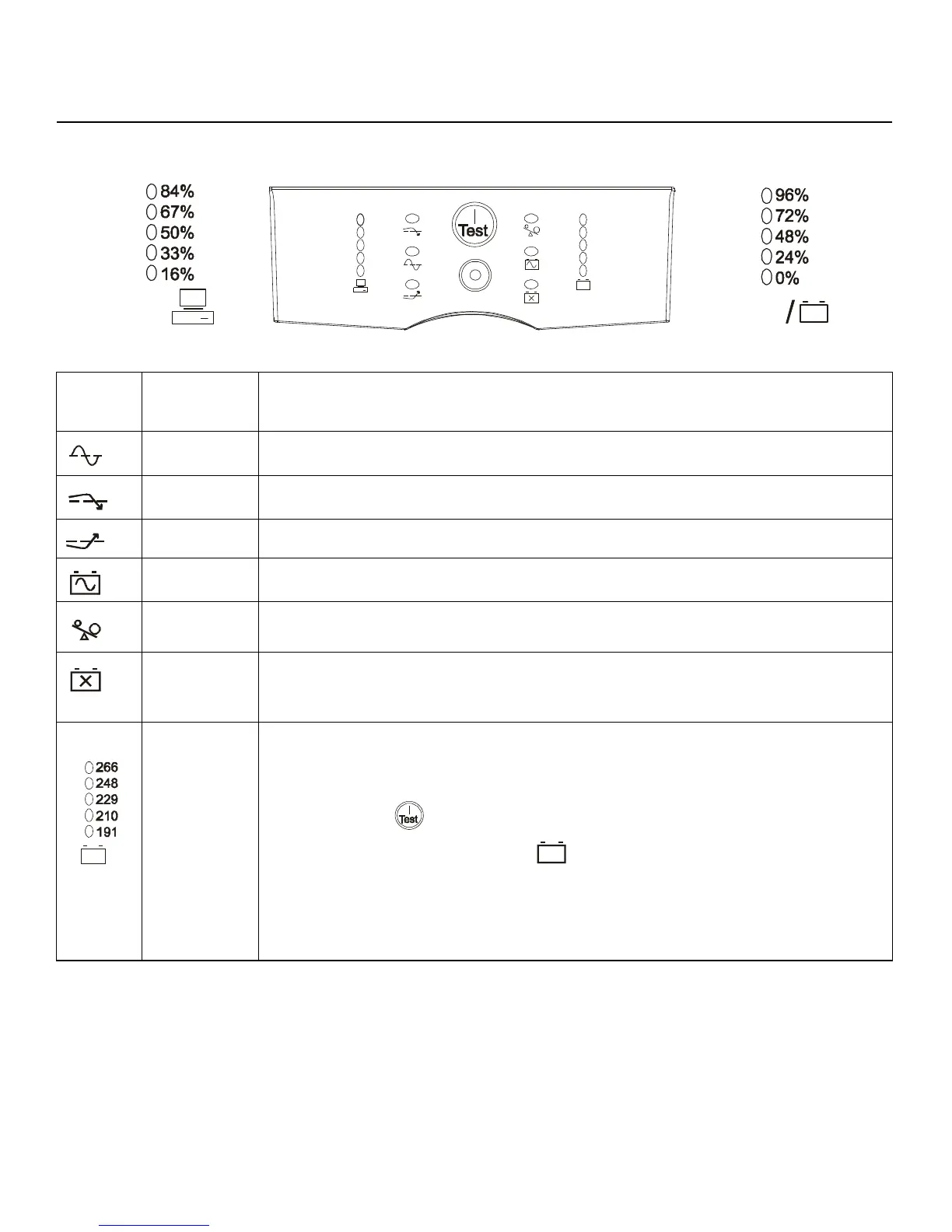
Display Panels
Display Panel Indicators and Function Buttons
Indicator
LED
Indicator
Title
Description
On Line The UPS is supplying utility power to the connected equipment, (see Troubleshooting).
AVR Trim The UPS is compensating for a high utility voltage.
AVR Boost The UPS is compensating for a low utility voltage.
On Battery The UPS is supplying battery power to the connected equipment.
Overload The connected equipment is drawing more than the UPS power rating allows, (see
Troubleshooting).
Replace
Battery/Battery
Disconnected
The battery is disconnected or must be replaced, (see Troubleshooting).
Diagnostic
Utility Voltage
The UPS has a diagnostic feature that indicates the utility voltage.
The UPS starts a self-test as part of this procedure. The self-test does not affect the voltage
display.
Press and hold the button to view the utility voltage bar graph indicator. After a few
seconds, this five-LED Battery Charge indicator on the right of the display panel will
show the utility input voltage.
Refer to the figure on the left for the voltage reading, (values are not listed on the UPS).
The indicator on the UPS shows the voltage is between the displayed value on the list and
the next higher value, (see Troubleshooting).
/
Load
Battery