EasyManuals Logo

APC Smart-UPS RC User Manual

APC Smart-UPS RC
21 pages
To Next Page IconTo Next Page
To Previous Page IconTo Previous Page
Page #4 background imageLoading...
Page #4 background image
User Manual Smart-UPS RC XLI/XLICH/XLI-CC 1000/2000/3000 VA 220/230/240 Vac Tower/Rack-Mount 4U 5
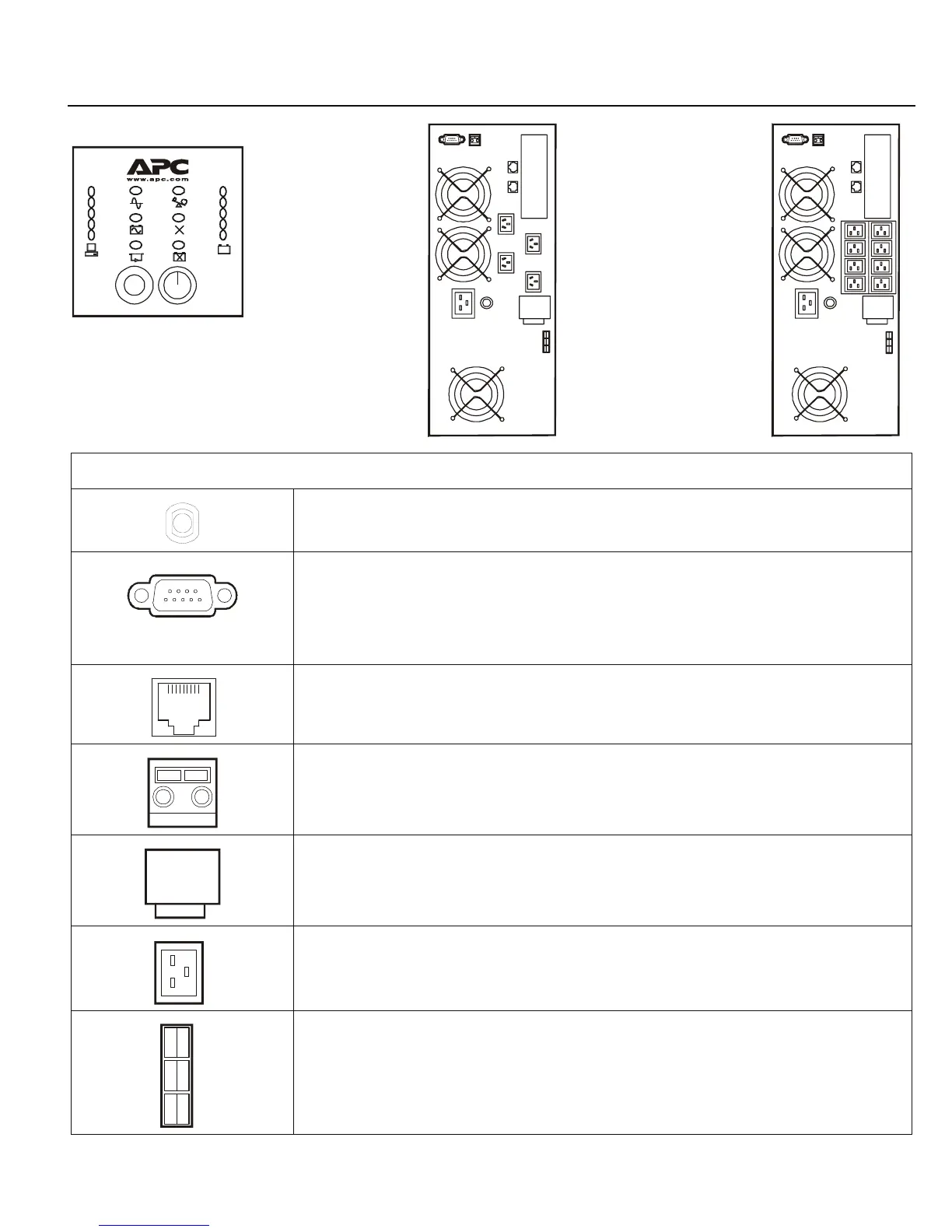
Front and rear panels
Rear panel Features
The input circuit breaker protects the UPS from extreme overload conditions.
Serial port for:
Power management software
Interface kits
Use only interface kits supplied or approved by APC. Any other serial interface
cable will be incompatible with UPS connector.
The UPS is equipped with surge protected Network In and Network Out connectors.
Emergency Power Off (EPO) terminal allows user to connect UPS to central EPO system.
Cover for output hardwire terminal block.
IEC320-C20
16 A current receptacles
External battery pack connector
Test
su0311a
su0312a
su0251a
Front Display Panel XLICH Model
Rear Panel
XLI/XLICH Model
Rear Panel
Output

Questions and Answers:

Question and Answer IconNeed help?

Do you have a question about the APC Smart-UPS RC and is the answer not in the manual?

APC Smart-UPS RC Specifications

General IconGeneral
Nominal Output Voltage230V
Nominal Input Voltage230V
Typical Recharge Time3 hours
Interface Port(s)SmartSlot, USB
TypeLine Interactive
Input Voltage Range160 - 286V
Output Voltage230V
Form FactorTower
Battery TypeMaintenance-free sealed Lead-Acid battery with suspended electrolyte
Output ConnectionsIEC 320 C13
Frequency50/60 Hz +/- 3 Hz
Communication PortsUSB
Input ConnectionsIEC-320 C14

Related product manuals