3.4 I/O Connection Considerations
Prior to installing the Aural Exciter Type III into your system, take note of
the following considerations for 1/O impedance matching and system
wiring.
3.4.1 Impedances
The input is of high (19.5 kOhms) impedance and may be easily driven by
any output source. If your source needs to see a 600 Ohm load, press the 600
OHM INPUT TERMINATION button located next to each audio input
(Fig-3-1.). Pressing the switch IN connects an internal 602 Ohm (1%) resistor
across pins 2 and 3 of the input XLR connector.
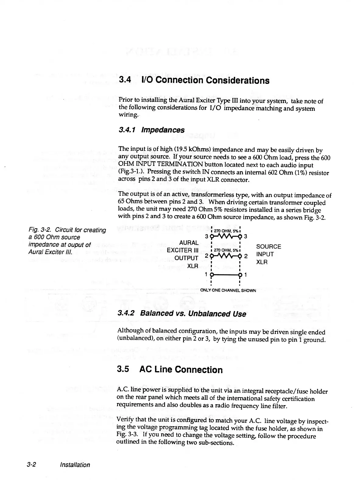
The output is of an active, transformerless type, with an output impedance of
65 Ohms between pins 2 and 3. When driving certain transformer coupled
loads, the unit may need 270 Ohm 5% resistors installed in a series bridge
with pins 2 and 3 to create a 600 Ohm source impedance, as shown Fig. 3-2.
3.4.2 Balanced vs. Unbalanced Use
Although of balanced configuration, the inputs may be driven single ended
(unbalanced), on either pin 2 or 3, by tying the unused pin to pin 1 ground.
3.5 AC Line Connection
A.C. line power is supplied to the unit via an integral receptacle/fuse holder
on the rear panel which meets all of the international safety certification
requirements and also doubles as a radio frequency line filter.
Verify that the unit is configured to match your A.C. line voltage by inspect
ing the voltage programming tag located with the fuse holder, as shown in
Fig. 3-3. If you need to change the voltage setting, follow the procedure
outlined in the following two sub-sections.
3-2
Installation